

Apparatus and method for hybrid computed tomography imaging
a computed tomography and apparatus technology, applied in tomography, instruments, nuclear engineering, etc., can solve the problems of limiting the total x-ray flux rate, image quality, and photon counting detectors
- Summary
- Abstract
- Description
- Claims
- Application Information
AI Technical Summary
Benefits of technology
Problems solved by technology
Method used
Image

Examples
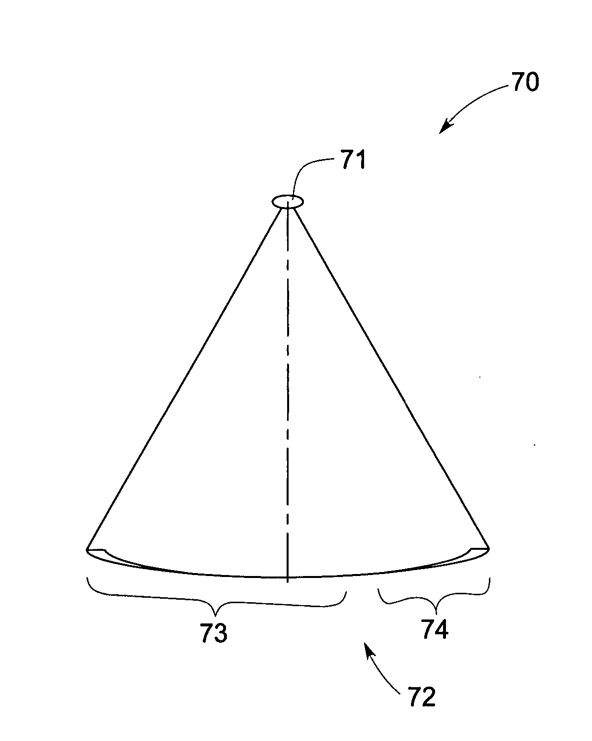
exemplary embodiment 70
[0056] Turning now to FIG. 3, an exemplary embodiment 70 of a detector arc for use in the imaging system of FIGS. 1-2 is illustrated. Reference numeral 71 represents a source of radiation, such as the source 12 (see FIG. 1). However, more than one source of radiation may be employed as will be described hereinafter. Furthermore, a non-symmetric detector arc 72 may include a plurality of energy discriminating detector elements 73 and a plurality of energy integrating detector elements 74. It may be noted that in certain embodiments each of the plurality of energy integrating detector elements 73 and each of the plurality of energy discriminating detector elements 74 may be representative of individual detector pixels. However, in certain other embodiments, each of the plurality of energy integrating detector elements 73 and each of the plurality of energy discriminating detector elements 74 may be representative of separate detectors. In certain embodiments, the energy integrating de...
exemplary embodiment 82
[0062] Referring now to FIG. 5, an exemplary embodiment 82 of a detector arc 84 is illustrated. Also, reference numeral 83 represents a source of radiation. The detector arc 84 may include a first side wing 85, a second side wing 86 and a center portion 87 disposed between the first and second side wings 85, 86. In a presently contemplated configuration, the first side wing 85 may include a first set of a plurality of energy integrating detector elements. In a similar fashion, the second wing 86 may include a second set of a plurality of energy integrating detector elements. Furthermore, the center portion 87 may include a plurality of energy discriminating detector elements. Reference numeral 88 is representative of a relatively large region of interest, while reference numeral 89 is representative of a relatively small region of interest. In addition, a portion of the X-ray beam which may be configured to illuminate the center portion 87 of the detector 84 is represented by refere...
PUM
 Abstract
Description
Claims
Application Information