Head assembly drive mechanism, head holder, magnetic head tester and magnetic disk tester

a drive mechanism and head holder technology, applied in the direction of functional testing of recording heads, instruments, magnetic properties, etc., can solve the problem of time-consuming reading/writing of test data, and achieve the effect of improving the response speed of the head and reducing the mass of the swing mechanism

Inactive Publication Date: 2007-09-06
HITACHI HIGH-TECH CORP
View PDF8 Cites 10 Cited by
  • Summary
  • Abstract
  • Description
  • Claims
  • Application Information

AI Technical Summary

Benefits of technology

[0016]As a result, according to the present invention which provides the swing mechanism utilizing elasticity of the member as the movable portion of the head assembly, it is possible to reduce the mass of the swing mechanism to thereby drive the head assembly at high speed and improve the response speed of the head in the ON track control. In the magnetic heads tester and the magnetic disk tester using the head assembly drive mechanism or the head holder, it is possible to dynamically position the head on substantially a center or a predetermined position of an aimed track precisely at high speed.

Problems solved by technology

Therefore, there is a problem that read / write of a test data takes time.

Method used


Image

  • Head assembly drive mechanism, head holder, magnetic head tester and magnetic disk tester
  • Head assembly drive mechanism, head holder, magnetic head tester and magnetic disk tester
  • Head assembly drive mechanism, head holder, magnetic head tester and magnetic disk tester

Examples


Embodiment Construction

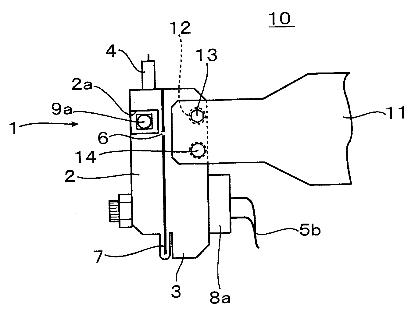
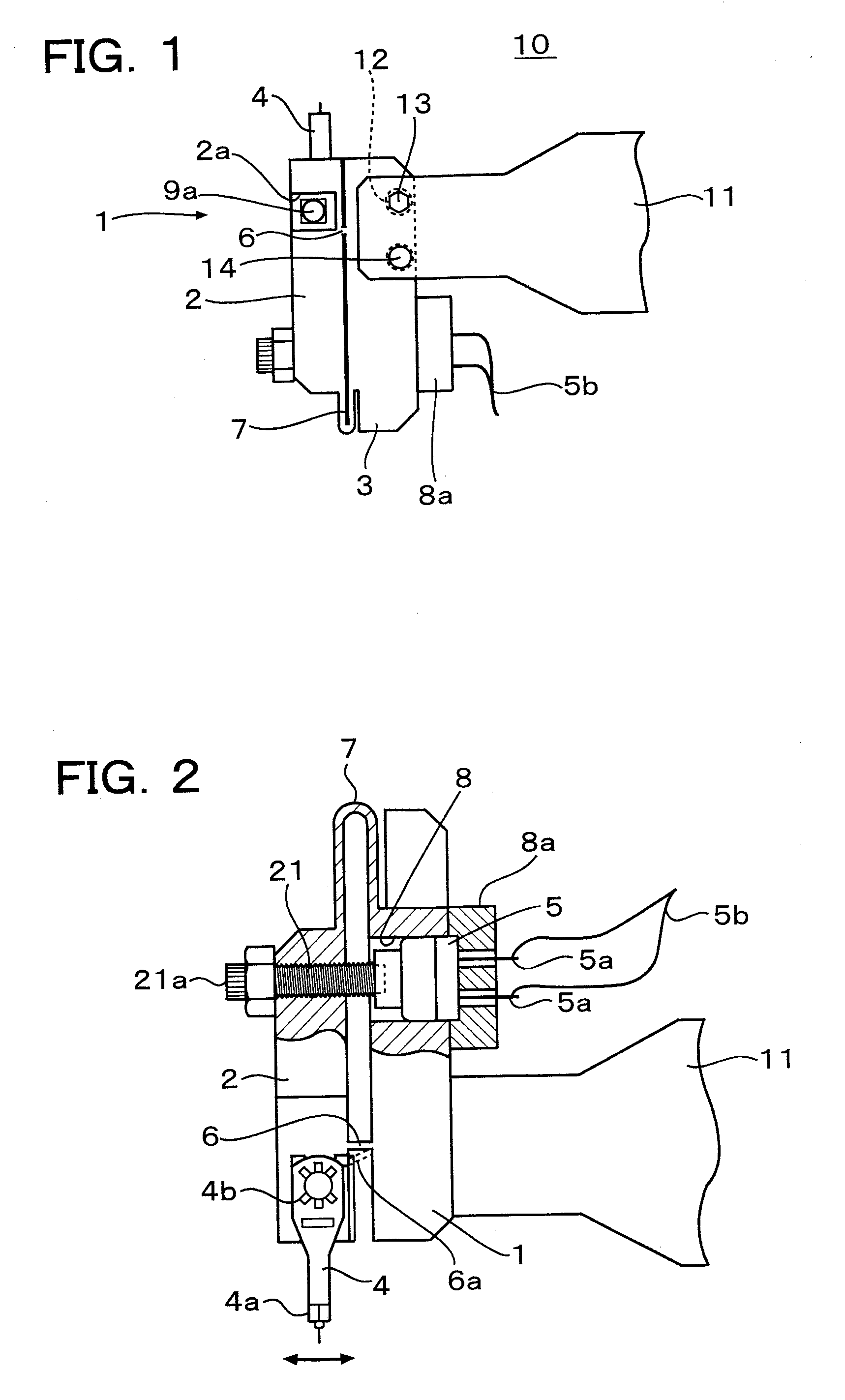
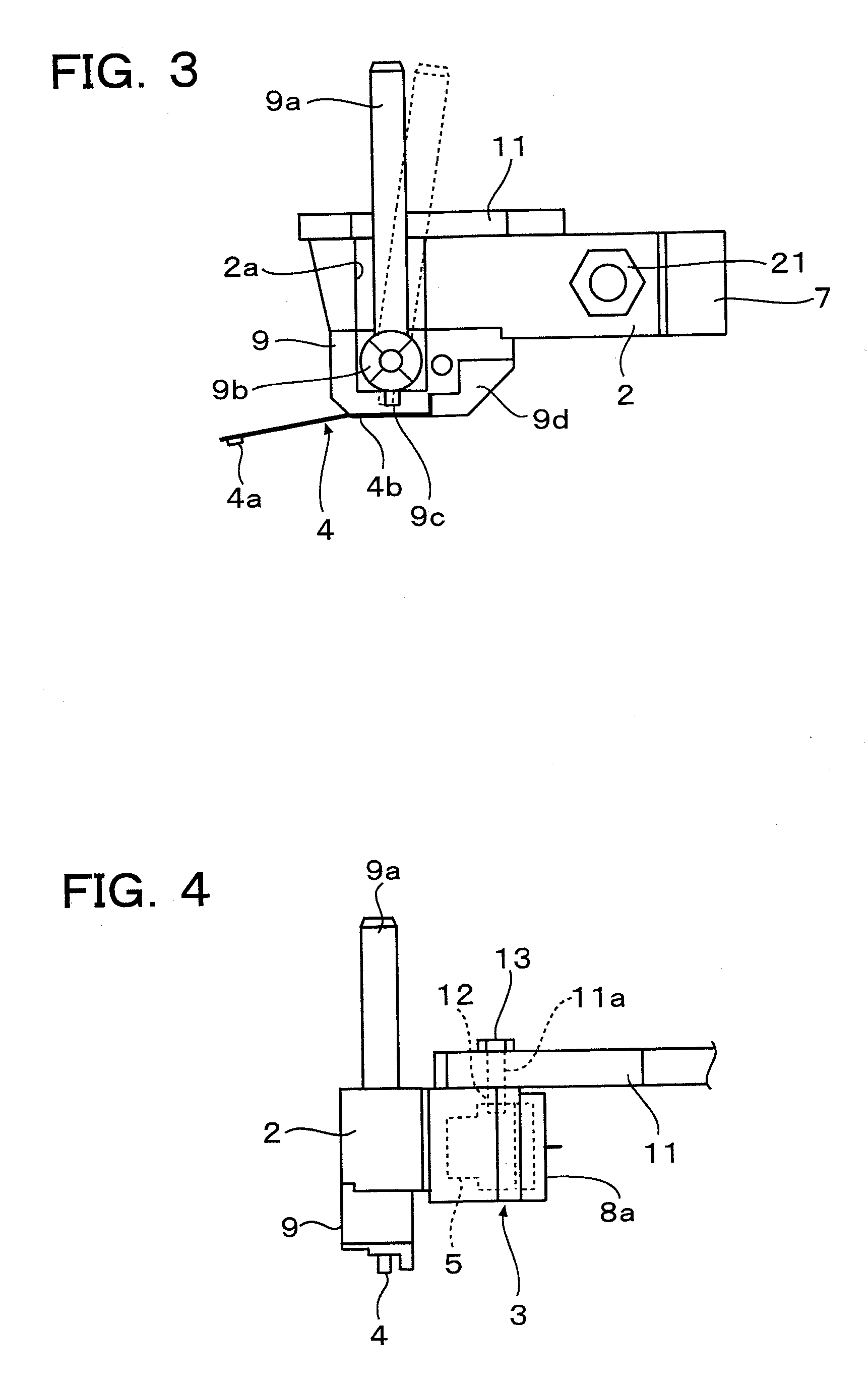
[0022]In FIGS. 1 to 4, a reference numeral 10 depicts a head assembly drive mechanism and 1 depicts a head holder in which the head assembly drive mechanism 10 is provided.

[0023]The head holder 1 is constructed with a single rectangular stainless steel (SUS) member as a whole and is divided to two blocks connected together by a flexible coupling portion 6. One of the blocks is a rectangular head assembly fixing block (first block) 2 and the other block is a rectangular support block (second block) 3 supporting the head assembly fixing block 2.

[0024]As shown in FIGS. 2 and 3, a head clamp mechanism 9 for detachably mounting a head assembly 4 is mounted on a lower surface of the head assembly fixing block 2 and the head assembly 4 is supported through the head clamp mechanism 9. A reference numeral 4a depicts a head and 4b a suspension spring.

[0025]As shown in FIG. 2, a piezo actuator 5 is fixedly provided within the support block 3, which is mounted on a head holder support arm 11.

[0...


PUM


Abstract

A head holder includes a first and second blocks connected each other with a predetermined gap between the blocks by a flexible coupling portion. The second block supports the first block swingably by increasing a width of either one of spaces of the predetermined gap on opposite sides of the coupling portion and narrowing the other space by bending the coupling portion by a piezo actuator. A magnetic head is dynamically moved in a direction crossing a track by swinging a head assembly fixed to the first block.

Description

TECHNICAL FIELD[0001]The present invention relates to a head assembly drive mechanism, a head holder, a magnetic head tester and a magnetic disk tester and, particularly, in a magnetic head tester or a magnetic disk tester for controlling a magnetic head to an ON track state according to a servo signal set correspondingly tracks on a magnetic disk, the present invention relates to a head assembly drive mechanism, in order to move the magnetic head in a direction traversing the tracks, a head assembly, which is constituted with a suspension spring and a magnetic head member and supports the magnetic head through the suspension spring, is dynamically swung by utilizing elastic bending of the magnetic head member to reduce a mass of a movable portion of the head assembly to thereby improve a response speed of the magnetic head in the ON track control.BACKGROUND ART[0002]Since the track width of a magnetic disk is decreased with increase of recording density in the magnetic disk device,...

Claims


Application Information

Patent Timeline
Patent Type & Authority Applications(United States)
IPC IPC(8): G01R33/12
CPCG11B5/455G11B5/4893G11B5/4826
Inventor YAMASAKI, FUJIO
Owner HITACHI HIGH-TECH CORP
Why Eureka
Try Eureka