Relay controller

Active Publication Date: 2007-09-06
EMERSON ELECTRIC CO
View PDF14 Cites 24 Cited by
  • Summary
  • Abstract
  • Description
  • Claims
  • Application Information

AI Technical Summary

Benefits of technology

[0004] The inventor hereof has succeeded at designing relay controllers and methods of operation that are capable of communicating a service requirement. The communicating of t

Problems solved by technology

The number of switches in its lifetime, along with conditions under which the relay is switched, causes the relay contacts to degrade.
The degrading of the relay contacts can cause failures of the relay to switch when command

Method used


Image

  • Relay controller
  • Relay controller
  • Relay controller

Examples


second embodiment

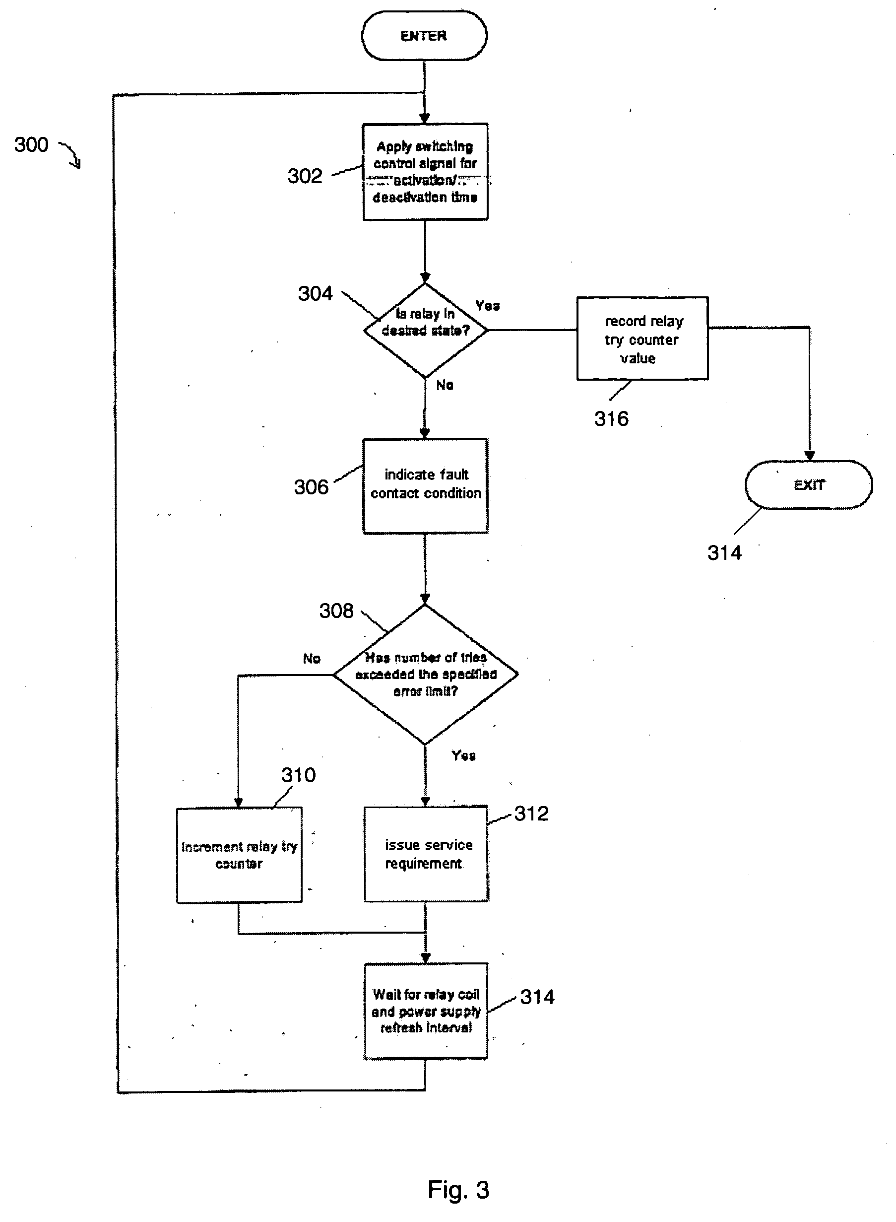
[0030] a method for controlling operation of a relay controller is generally referenced at 300 as shown in FIG. 3. The method begins by applying a switch signal to the relay at step 302, and then compares the expected state of the relay contacts to an actual state of the relay contacts at step 304. If no disparity exists between the actual state of the relay contacts and the expected state of the relay contacts, the method proceeds to 318 (the relay try counter is at zero at step 316 if contacts are in expected state). If a disparity is detected at step 304, the method indicates or communicates the fault condition at step 306. At step 310, the method also increments the number of tries, or times that the relay is signaled or pulsed to switch the relay to a desired state. At step 314, a refresh interval is applied before returning to step 302 to repeat the signal for switching the relay contacts. The method determines whether the relay pulse counter has reached a predetermined maximu...

third embodiment

[0034] a method for controlling the operation of a relay controller is generally referenced at 500 as shown in FIG. 5. The method is adapted to control switching of a relay to close the relay contacts connected to a power source at a minimum voltage potential, or near the crossing of the voltage waveforms. The method comprises an offset sequence 500 that includes monitoring the contact closure of the relay with respect to the crossing of the waveforms of the power source, and adjusting the time offset to minimize the time difference between the contact closure and the crossing of the waveforms. The time offset is a variable time value that is tuned to ensure that the closure of the contacts and the waveform-crossing coincide. The method also includes utilizing the time value or offset in commanding a closing of the contacts of the relay. The time value for commanding a closing of the contacts of the relay allows the contact closure to coincide with the waveform-crossing of the power...

ninth embodiment

[0039] Referring to FIG. 9, a graph illustrates a method for operating a relay controller. The processing device commands the switching of the relay contacts as required for the application. The method comprises detecting a first fault weld condition by a disparity between an expected position of the relay and the actual position of the relay, and storing the number of switches (or cycles) the relay made as of the contact weld fault condition. The method pulses the relay a number of times until the weld condition is overcome, and stores the number of pulses required to overcome the welded contact failure condition. The method then calls for detecting a second weld condition and storing the number of relay switches when the weld condition occurred, subsequently pulsing the relay a number of times until the second weld condition is overcome, and stores the number of pulses required to overcome the second weld condition. The method also provides for determining a predicted failure of t...


PUM


Abstract

A relay controller for connecting a power source includes at least one relay having at least two contacts. The relay controller includes a processing device operable to selectively switch the relay contacts, and a feedback circuit adapted to identify an actual state of the relay contacts. The processing device is configured to recognize a fault contact condition of a disparity between an expected state of the relay contacts and the actual state of the relay contacts. The processing device is also configured to responsively communicate information relating to the relay fault condition.

Description

FIELD OF THE INVENTION [0001] The present invention relates generally to relay controllers, and more particularly to communicating relay controllers. BACKGROUND OF THE INVENTION [0002] A relay controller circuit may generally include a processing device and a relay having contacts. The contacts are driven by the processing device to an open position or a close position, depending on the desired output of the relay. In various applications of the relay controller, the relay may be switched frequently throughout its lifetime. The number of switches in its lifetime, along with conditions under which the relay is switched, causes the relay contacts to degrade. [0003] The degrading of the relay contacts can cause failures of the relay to switch when commanded by the processing device. The failure may momentarily interrupt normal relay switching operation, or may be permanent. Depending on the degradation of the relay contacts, the relay may still be able to switch and function in the deg...

Claims


Application Information

Patent Timeline
IPC IPC(8): G01R31/327G01R31/02
CPCG01R31/3278
Inventor DRAKE, DEAN A.MUELLER, GREGGHENDRIX, GEORGE E.
Owner EMERSON ELECTRIC CO
Why Eureka
Try Eureka