Tire Slip State Detecting Method And Tire Slip State Detecting Apparatus

a technology of slip state detection and tire slip, which is applied in vehicle tyre testing, instruments, roads, etc., can solve the problems of reducing the accuracy of detecting the slip region, suppressing the slip behavior, and slipping slip behavior, so as to achieve efficient and accurate identification of the slip region, the effect of high accuracy

Active Publication Date: 2007-09-06
THE YOKOHAMA RUBBER CO LTD
View PDF8 Cites 25 Cited by
  • Summary
  • Abstract
  • Description
  • Claims
  • Application Information

AI Technical Summary

Benefits of technology

[0036] In the present invention, since the contact region of the tire is identified from the measurement data of acceleration in the radial direction of the tire, by using the identified region, the slip state in the contact region can be efficiently identified from the measurement data of acceleration.
[0037] In this case, identification of the slip state can be achieved with high accuracy because high frequency components of a specified frequency band are extracted from the acquired measurement data of acceleration of the tire, preferably, from the acquired measurement data of acceleration in the width direction of the tire, and the slip region is identified based on the amplitude level in the high frequency components. In particular, efficient and accurate identification of the slip region is achieved by determining the slip region if the frequency of occurrences in which the amplitude level of the high frequency components exceeds a reference value is higher than a predetermined frequency.

Problems solved by technology

As the slip angle increases, the adhesion region is decreased while the slip region is increased, which finally leads to the whole contact region of the tire becoming the slip region, and the tire as a whole causing slide slipping (slide slip behavior).
Generally, the slide slip behavior is difficult for the vehicle driver to detect, and moreover, once the slide slip behavior occurs, suppressing the slide slip behavior to restore the steering under control is almost impossible.
Consequently, the vehicle experiences out of steering control which in turn could result in a vehicle crash.
However, since such control is achieved by measuring the forces and speeds that are applied to the tire as a whole, it has not always been able to estimate the occurrence of the slide slip behavior with accuracy.
Particularly, it has been unable to estimate the slide slip behavior based on information of the slip region in the contact region of the tire.
However, any one of the Patent Documents 1 to 3 does not allow detection of a slide slip state from the measurement data of acceleration, though it is possible to estimate the status of the road surface using the measurement data.

Method used


Image

  • Tire Slip State Detecting Method And Tire Slip State Detecting Apparatus
  • Tire Slip State Detecting Method And Tire Slip State Detecting Apparatus
  • Tire Slip State Detecting Method And Tire Slip State Detecting Apparatus

Examples


Embodiment Construction

[0060] Hereinafter, the tire slip state detecting method and the tire slip state detecting apparatus according to the present invention will be described in detail with reference to the preferred embodiments shown in the attached drawings.

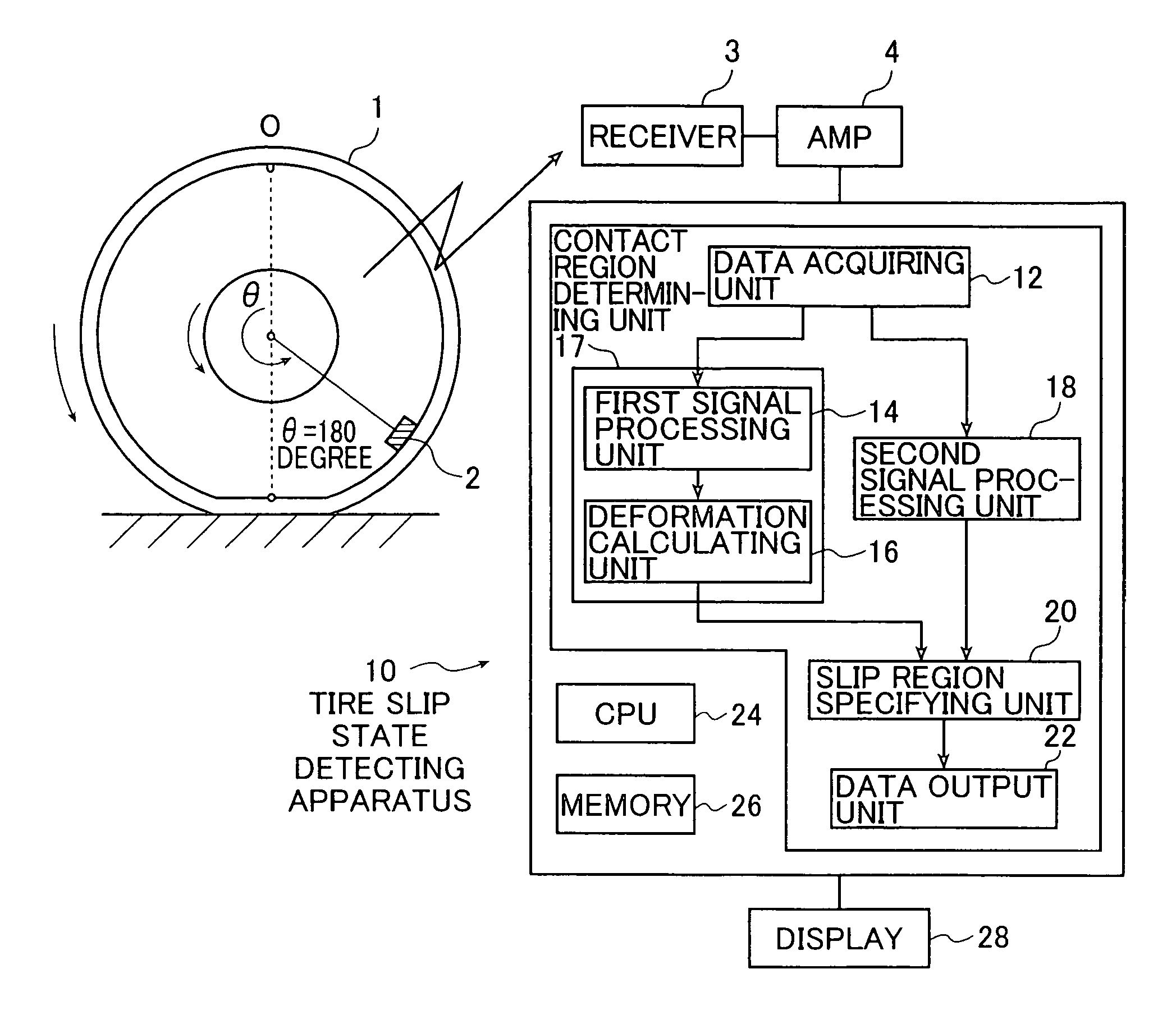
[0061]FIG. 1 is a block diagram showing a structure of an embodiment of the tire slip state detecting apparatus according to the present invention that implements the tire slip state detecting method according to the present invention.

[0062] A tire slip state detecting apparatus 10 shown in FIG. 1 is an apparatus for detecting a slip state in a contact region of a tire 1 by using measurement data of acceleration obtained at a tread portion of the tire 1. The acceleration at the tread portion of the tire 1 is the measurement data of acceleration that has been detected by an acceleration sensor 2 fixed on an inner circumference surface in a tire cavity region of the tire and amplified by an amplifier 4. The measurement data acquired by the accelera...


PUM


Abstract

To detect a slip state in a contact region of a rotating tire on a road surface, first, the first radical direction data and the second width direction data of measurement data of acceleration at a tread portion of the rotating tire for a duration corresponding to one round of tire rotation are acquired. Second, time series data of acceleration due to tire deformation is extracted from the first radical direction data and displacement data is obtained by subjecting the time series data of acceleration due to tire deformation to a time integration of second order, thereby a deformation at the tread portion is calculated and a contact region of the rotating tire is determined from the calculated deformation. Next, from the second width direction data, a slip region within the determined contact region is specified based on vibration level of the second data.

Description

TECHNICAL FIELD [0001] The present invention relates to a tire slip state detecting method for detecting a slip state in a contact region of a tire which is rotating on a road surface, and an apparatus implementing the method. BACKGROUND ART [0002] When a vehicle makes a turn, a tread portion of a tire that has a slip angle slips partially against the road surface. In other words, in a contact region of the tread portion of the tire, there mixedly exist a region (adhesion region) in which the tread portion adheres to the road surface and a region (slip region) in which the tread portion slips against the road surface. As the slip angle increases, the adhesion region is decreased while the slip region is increased, which finally leads to the whole contact region of the tire becoming the slip region, and the tire as a whole causing slide slipping (slide slip behavior). [0003] Generally, the slide slip behavior is difficult for the vehicle driver to detect, and moreover, once the slide...

Claims


Application Information

Patent Timeline
Patent Type & Authority Applications(United States)
IPC IPC(8): B60W40/06B60C19/00B60C23/00B60W40/068B60W40/10B60W40/12G01M17/02
CPCB60G2204/113B60G2400/10B60G2400/822B60G2800/21B60G2800/702B60W2520/26B60T8/17616B60T2240/04B60W40/06B60W2422/70B60T8/173
Inventor MATSUDA, JUNKITAZAKI, TSUYOSHIMIYASHITA, NAOSHIHASHIMURA, YOSHIAKIHATTORI, YUTAKA
Owner THE YOKOHAMA RUBBER CO LTD
Why Eureka
Try Eureka