Pulse damped fluidic architecture

Active Publication Date: 2007-09-06
MEMJET TECH LTD
View PDF12 Cites 12 Cited by
  • Summary
  • Abstract
  • Description
  • Claims
  • Application Information

AI Technical Summary

Benefits of technology

[0014] the pulse damper decreases the amplitude of pressure pulses in the ink.
[0016] Adding a pulse damper to the fluidic architecture accepts that sharp pressure pulses in the ink may occur but by damping them, the pressure amplitude is less capable of flooding or depriming the MEMS printhead. Furthermore, most pulse damping mechanisms can also serve as a purge mechanism for dealing with colour mixing or depriming.

Problems solved by technology

Adding a pulse damper to the fluidic architecture accepts that sharp pressure pulses in the ink may occur but by damping them, the pressure amplitude is less capable of flooding or depriming the MEMS printhead.

Method used


Image

  • Pulse damped fluidic architecture
  • Pulse damped fluidic architecture
  • Pulse damped fluidic architecture

Examples


Embodiment Construction

[0037] The fluidic system of an inkjet printer using pagewidth inkjet printheads of the type developed by the Assignee, should satisfy several requirements. In particular, most printing applications will require some regulation of ink pressure at the printhead, provision for long term ink storage, printhead IC maintenance and the volumetric control of ink supply.

[0038] It is important to note that references to ‘ink’ throughout this specification should be interpreted as a functional fluid encompassing all types of printable fluid regardless of whether it is colored and intended to form visible images or indicia on a media substrate. The printhead may also eject infra-red ink, adhesive or a component thereof, medicament, volatile aromatic or any other functionalized fluid.

Fluidic System Overview

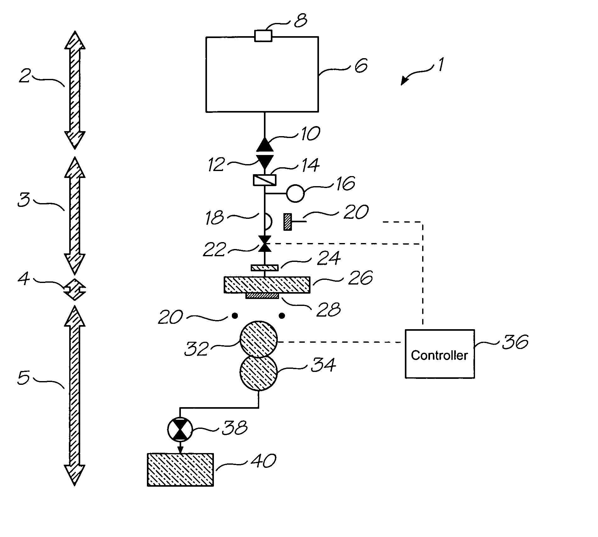
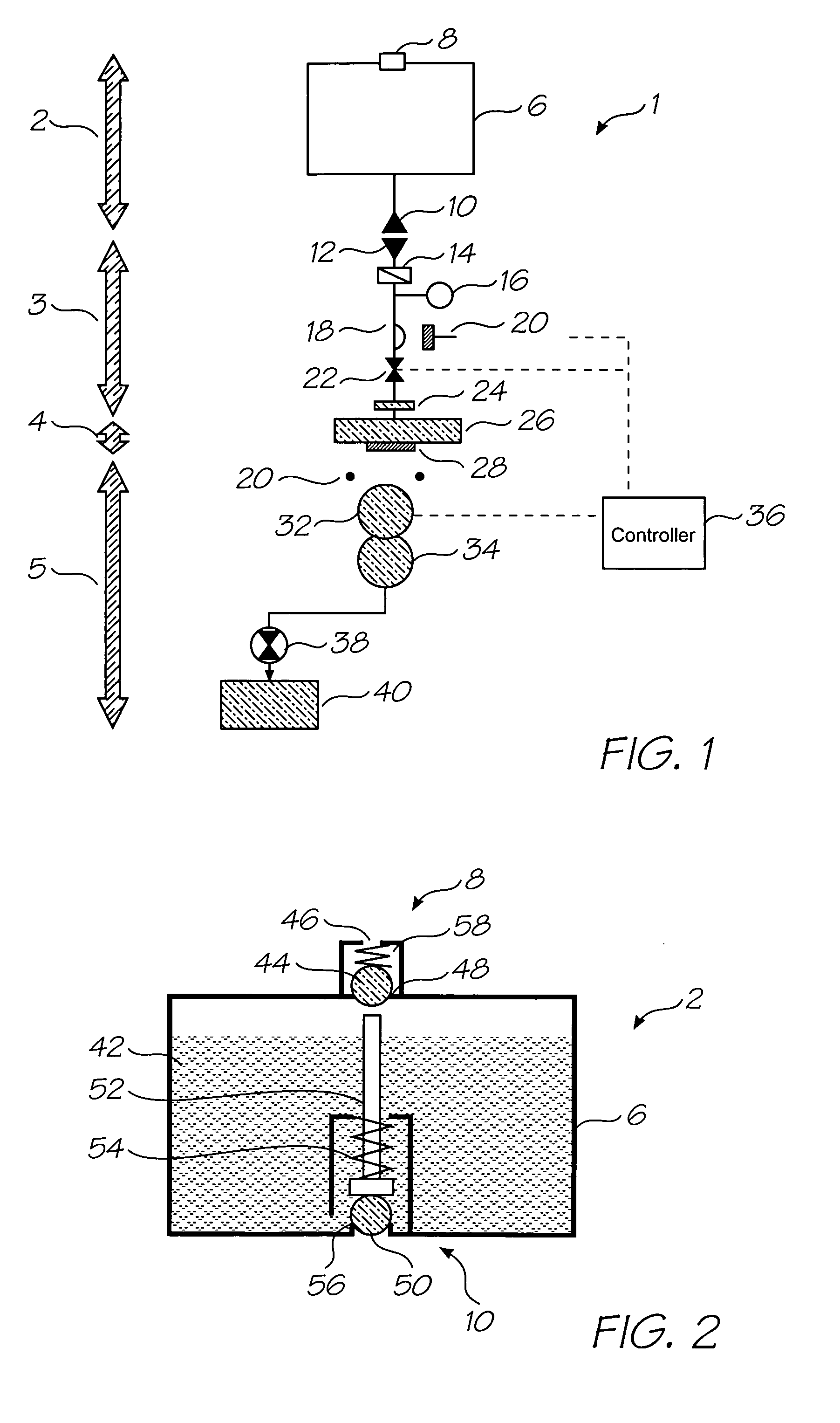
[0039]FIG. 1 is a schematic overview of the fluidic system 1 in an inkjet printer. The system 1 has been divided into four sections; the ink tank 2, ink line and conditioning 3, printhead...


PUM


Abstract

An inkjet printer with a printhead integrated circuit (IC) (28), an ink supply reservoir (6) for storing ink, an ink supply line (3) defining a flow path from the ink supply reservoir to the printhead IC (28). A pulse damper (16) positioned along the flow path to decrease the amplitude of pressure pulses in the ink.

Description

CROSS REFERENCE TO RELATED APPLICATIONS [0001] Various methods, systems and apparatus relating to the present invention are disclosed in the following U.S. Patents / Patent Applications filed by the applicant or assignee of the present invention: 09 / 517539656685863319466246970644252509 / 51738409 / 505951637435409 / 517608681696867578326334190674533109 / 51754110 / 20355910 / 20356010 / 20356410 / 63626310 / 63628310 / 86660810 / 90288910 / 90283310 / 94065310 / 94285810 / 72718110 / 72716210 / 72716310 / 72724510 / 72720410 / 72723310 / 72728010 / 72715710 / 72717810 / 72721010 / 72725710 / 72723810 / 72725110 / 72715910 / 72718010 / 72717910 / 72719210 / 72727410 / 72716410 / 72716110 / 72719810 / 72715810 / 75453610 / 75493810 / 72722710 / 72716010 / 93472011 / 21270211 / 27249110 / 296522679521510 / 29653509 / 5751096805419685928969777516398332639457366229236747760692114410 / 88488110 / 94394110 / 94929411 / 03986611 / 1230116986560700803311 / 14823711 / 24843511 / 24842610 / 92284610 / 92284510 / 85452110 / 85452210 / 85448810 / 85448710 / 85450310 / 85450410 / 85450910 / 85451010 / 85449610 / 85449710 / 85449...

Claims


Application Information

Patent Timeline
IPC IPC(8): B41J2/175
CPCB41J2/155B41J2/16526B41J2/1707B41J2/175B41J2/17509B41J2202/20B41J29/08B41J2002/14419B41J2002/14459B41J2202/19B41J2/17596
Inventor BROWN, BRIAN ROBERTMORGAN, JOHN DOUGLAS PETERSILVERBROOK, KIA
Owner MEMJET TECH LTD
Why Eureka
Try Eureka