Blind identification of advanced modulation and coding modes

a technology of advanced modulation and coding mode, applied in the field of communication systems, can solve the problems of receivers b>108/b> not being able to process signals, and increasing the probability of data transmission interference,

Active Publication Date: 2007-09-06
DIRECTV LLC
View PDF4 Cites 70 Cited by
  • Summary
  • Abstract
  • Description
  • Claims
  • Application Information

AI Technical Summary

Problems solved by technology

Such interference is called “co-channel” interference, where one channel of data interferes with the reception and demodulation of another channel of data.
As communications systems 100 transmits more data, i.e., more channels of programming on a satellite broadcast system that are viewable on monitor 206, the probability of in

Method used


Image

  • Blind identification of advanced modulation and coding modes
  • Blind identification of advanced modulation and coding modes
  • Blind identification of advanced modulation and coding modes

Examples


Embodiment Construction

[0046] In the following description, reference is made to the accompanying drawings which form a part hereof, and which show, by way of illustration, several embodiments of the present invention. It is understood that other embodiments may be utilized and structural changes may be made without departing from the scope of the present invention.

Overview

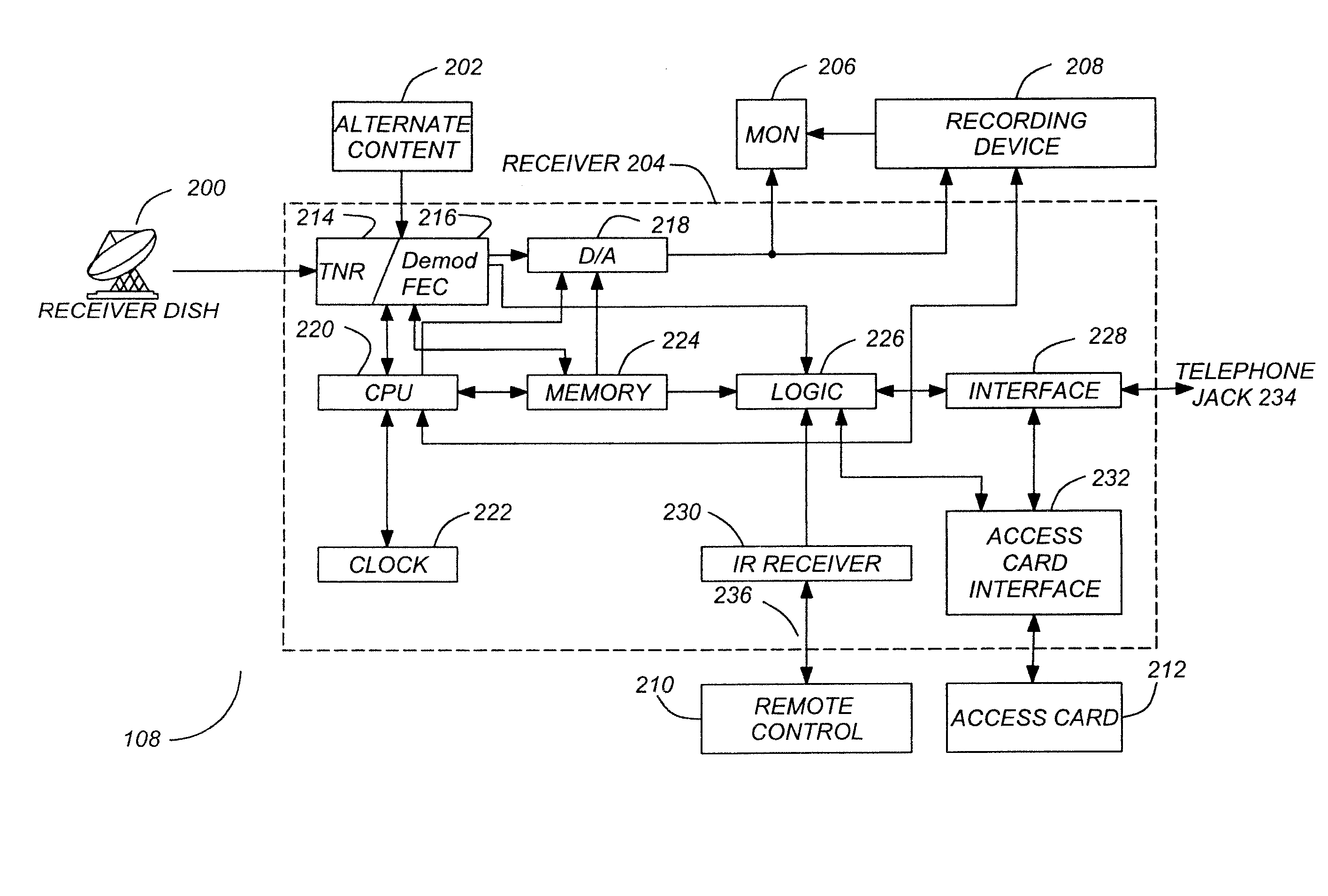
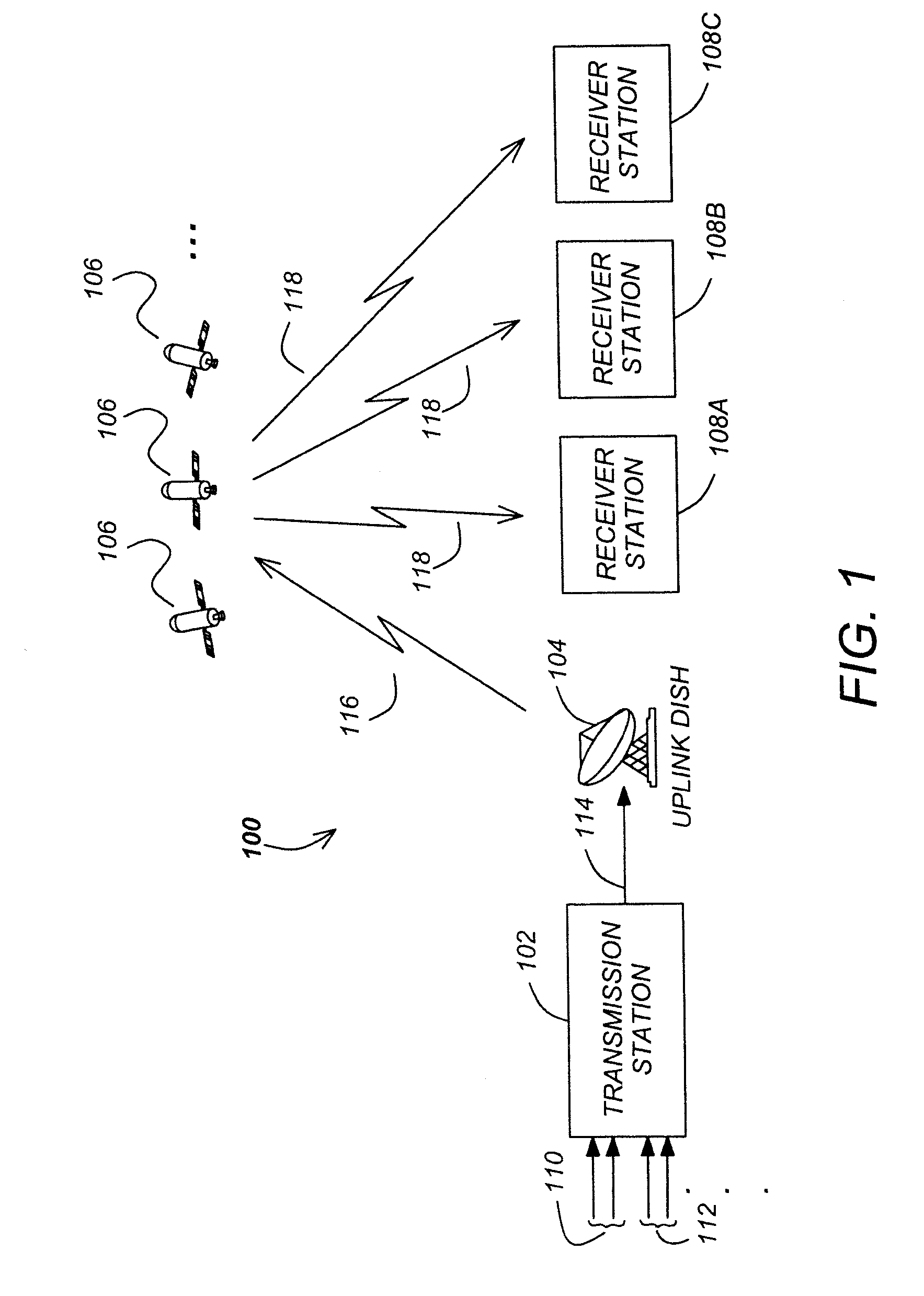
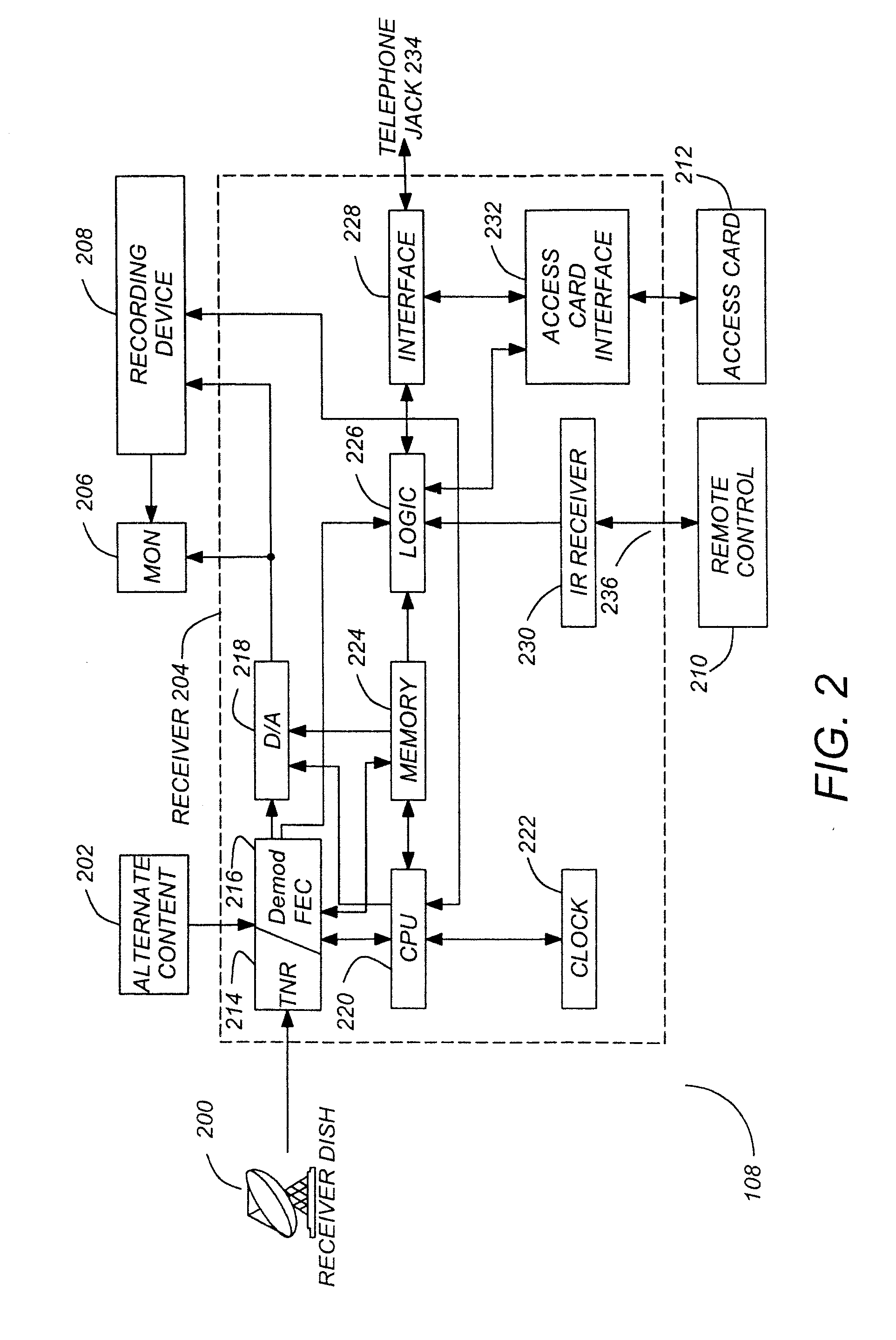
[0047] In the present invention, the digital data transmitted from transmission station 102 via signal 114, satellites 106, and signal 118. The digital data contains three main components: a header portion of a data frame, called the physical layer header or PL header; payload data; and optionally, additional inserted symbols, called pilot symbols, which are used by the receiver 108 to mitigate the deleterious effects of degradation in the receiver station 108, primarily phase noise. By using the PL header, the demodulator / FEC-decoder 216 can quickly acquire the correct phase and frequency at the beginning of every data frame. For ma...


PUM


Abstract

Methods and apparatuses for acquiring and demodulating a data stream transmitted in a communication system. A method in accordance with the present invention comprises finding a boundary of a physical layer frame (PLFrame) in the data stream, finding a first 26 bits of a Unique Word (UW) associated with the data stream, finding a scrambling code utilizing the UW, and using a decoding procedure to determine a modulation type and code rate used for desired signals within the data stream.

Description

CROSS-REFERENCE TO RELATED APPLICATIONS [0001] This application claims the benefit under 35 U.S.C. § 119(e) of co-pending and commonly-assigned U.S. provisional patent application Ser. No. 60 / 771,394, filed Feb. 8, 2006, entitled “BLIND IDENTIFICATION OF ADVANCED MODULATION AND CODING MODES,” by Joseph Santoru et al., which application is incorporated by reference herein.BACKGROUND OF THE INVENTION [0002] 1. Field of the Invention [0003] The present invention relates to communication systems, and more particularly to methods and apparatuses for minimizing signal interference. [0004] 2. Description of the Related Art [0005]FIG. 1 illustrates a typical satellite television system of the related art. [0006]FIG. 1 shows a communications system, specifically a television broadcasting system 100, which transmits and receives audio, video, and data signals via satellite. Although the present invention is described in the context of a satellite-based television broadcasting system, the tech...

Claims


Application Information

Patent Timeline
IPC IPC(8): H04J3/00H04H20/00H04N5/00H04N5/44H04N7/24
CPCH04N21/4382H04N21/4385H04N21/6143H04L1/0046H04L1/0057H04L1/0072H04L7/04H04L27/0012H04N5/4401H04N7/20H04N21/2383H04N21/2389H04N21/434H04L25/03866H04N21/426H04L25/00H04L65/00
Inventor SANTORU, JOSEPHZHOU, GUANGCAICHEN, ERNEST C.LAI, DENNISMAITRA, SHAMIK
Owner DIRECTV LLC
Why Eureka
Try Eureka