
System and Method for Location Identification

a technology of location identification and system, applied in the field of physical location identification, can solve problems such as delay or complete lack of response, difficulty in handling emergency calls, and not designed to support the delivery of crucial location information

Inactive Publication Date: 2007-09-06
MICROSEMI
View PDF16 Cites 37 Cited by
  • Summary
  • Abstract
  • Description
  • Claims
  • Application Information

AI Technical Summary

Benefits of technology

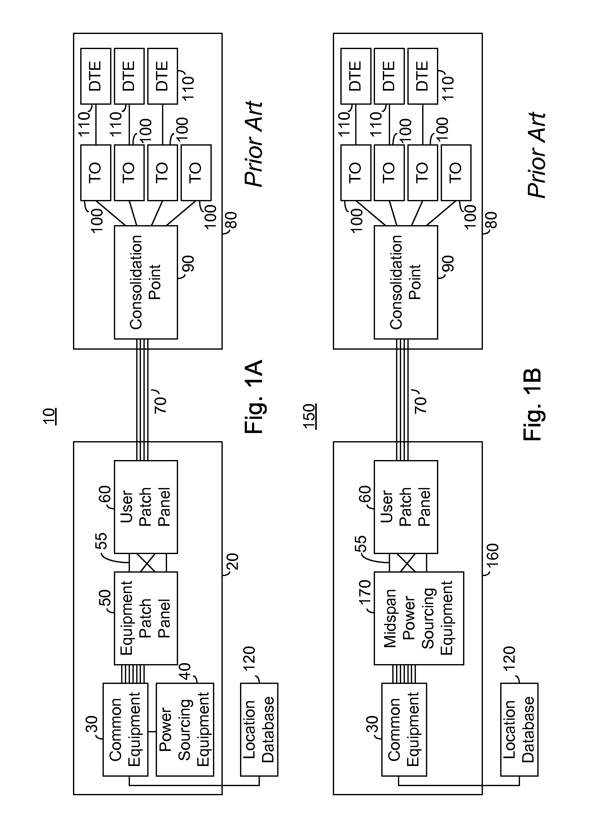
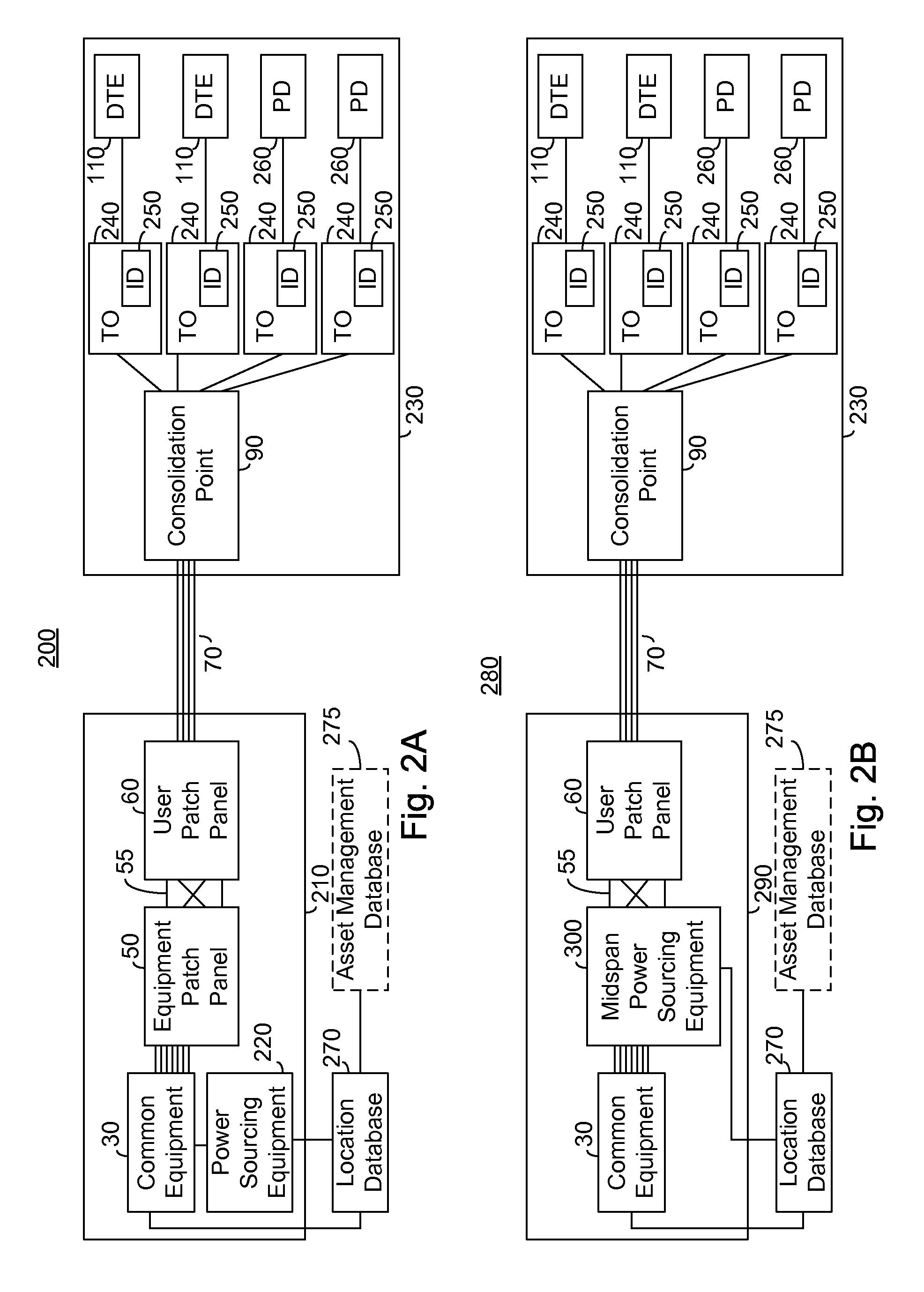
[0015]In one further embodiment each equipment type between the voltage source and the DTE or PD is provided with a location identifier. The location identifier is provided with information indicating the type of equipment to which it is associated as well as a multi-bit location data. The current limited voltage source signals the location identifier associated with each type of equipment to transmit in turn its multi-bit location data and monitors the resultant current flow to detect and receive the resultant transmission. In response to the received multi-bit location data of each type of equipment connected to a port of the voltage source, the complete path between the voltage source and the TO is identified automatically and communicated to the database. Such an embodiment advantageously provides complete asset management between the voltage source and the TO.

Problems solved by technology

One downside of the expanding use of VoIP is the difficulty in handling emergency calls, and in particular identifying the location of callers to emergency services.
Unfortunately, VoIP, which allows for voice to be handled over data connections, is not designed to support delivering the crucial location information.
In the event of an emergency call, the PSAP in the wrong city would then be notified, resulting in a delayed response or complete lack of response, from emergency services.
Unfortunately, this is a manual task separate and apart from the reconnection, and is thus liable to be neglected or in error.
Such a requirement adds cost, and reduces flexibility.
Unfortunately, prior art methods rely on a human update of any changes in the connection between the common equipment port and the VoIP Endpoint.
In the event that these changes, which commonly occur when moving or changing location of personnel, and are commonly known as “moves, adds and changes”, are not properly reflected in the location database or location information server (LIS) the location information sent by the VoIP endpoint will be in error.
Such an error may result in a delay in the provisioning of life saving emergency services.
The requirement for an Ethernet controller adds to the expense of such a solution.
Additionally, asset management functionality is accomplished with a plurality of sender tags and a decoder plug associated with a computer or other DTE, and an immovable object, which is costly and difficult to implement.

Method used


Image

  • System and Method for Location Identification
  • System and Method for Location Identification
  • System and Method for Location Identification

Examples


first embodiment

[0102]FIG. 2C illustrates a high level flow chart of the operation of the system of FIGS. 2A and 2B in accordance with a principle of the invention. In stage 1200, a multi-bit location data code for each TO 240 within system 200, 280 associated with the respective physical location is stored in location database 270. In the event one or more TO 240 within system 200, 280 is loaded with geographic data as described above, stage 1200 is not required for that TO 240. In an exemplary embodiment stage 1200 is accomplished manually or semi-manually at time of installation, with any updates being similarly accomplished manually or semi-manually as incurred.

[0103]In stage 1210 powering ports of endpoint PSE 220 or midspan PSE 300, respectively, associated with ports of common equipment 30 are stored in location database 270. Endpoint PSE 220 and midspan PSE 300 are collectively hereinafter referred to as a PSE. In an exemplary embodiment stage 1210 is accomplished manually or semi-manually ...

second embodiment

[0112]FIG. 2D illustrates a high level flow chart of the operation of the system of FIGS. 2A and 2B in accordance with a principle of the invention. In stage 1500 a multi-bit location data code for each TO 240 within system 200, 280 associated with the respective physical location is stored in location database 270. In the event one or more TO 240 within system 200, 280 is loaded with geographic data as described above, stage 1500 is not required for that TO 240. In an exemplary embodiment stage 1500 is accomplished manually or semi-manually at time of installation, with any updates being similarly accomplished manually or semi-manually as incurred.

[0113]In stage 1510 powering ports of endpoint PSE 220 or midspan PSE 300, respectively, associated with ports of common equipment 30 are stored in location database 270. In an exemplary embodiment stage 1510 is accomplished manually or semi-manually at time of installation, with any updates being similarly accomplished manually or semi-m...

third embodiment

[0134]FIG. 3C illustrates location identifier 250 of FIGS. 2A, 2B in accordance with a principle of the invention comprising an interface 550 and a transmitting module 410. Interface 550 comprises: a diode bridge 440; a first and second impedance 560; and an impedance 570. Transmitting module 410 comprises: a control 450; an electronically controlled switch 460; a multi-bit location data storage 470; and a current modulator 480. A single interface 550 connected to two twisted wire pairs are shown, however this is for ease of illustration and is not meant to be limiting in any way. Preferably a pair of interfaces 550 are supplied, a first interface 550 being attached to the data pairs (equivalent to RJ-45 pins 1, 2, 3 and 6 as described in IEEE 802.3af) and a second interface 550 being attached to the spare pairs (equivalent to RJ-45 pins 4, 5, 7 and 8 as described in IEEE 802.3af).

[0135]First impedance 560 is connected between a first conductor, labeled conductor a1, of a first pair...


PUM


Abstract

A system for location identification in a local area network comprising: a current limited voltage source; a telecommunications outlet; communication cabling connecting the current limited voltage source to the telecommunications outlet; and a location identifier associated with the telecommunications outlet, the location identifier being responsive to a pre-determined voltage level from the current limited voltage source to transmit a multi-bit location data. In one embodiment the multi-bit location data is received at the power sourcing equipment and in another embodiment the multi-bit location data is received at a data terminal equipment connected to the telecommunications outlet.

Description

CROSS-REFERENCE TO RELATED APPLICATION[0001]This application claims priority from provisional U.S. Patent Application Ser. No. 60 / 775,776 filed Feb. 23, 2006 entitled “System and Method for Location Identification” the entire contents of which is incorporated herein by reference.BACKGROUND OF THE INVENTION[0002]The present invention relates to the field of physical location identification suitable for use with emergency services, and more particularly to a system and method of providing an identifier associated with a fixed physical location of a wall jack.[0003]The use of local area networks, and in particular Ethernet based networks, continues to expand. Additionally, telephony utilizing voice over Internet protocol (VoIP) is rapidly becoming common for new workplace installations at least in part due to its reduced cost of installation and flexibility. VoIP advantageously is powered by power over Ethernet (PoE), as embodied in the IEEE 802.3af-2003 standard, published by the Inst...

Claims


Application Information

Patent Timeline
IPC IPC(8): H04M1/56H04M15/06
CPCH04L12/10H04M1/2535H04L67/18H04M15/06H04M11/04H04L67/52
Inventor PINCU, DAVIDBLAUT, RONIDARSHAN, YAIR
Owner MICROSEMI
Learn More