
Interference mitigation in a wireless communication system

a wireless communication system and interference mitigation technology, applied in the field of communication systems, can solve the problems of significant interference from transmissions associated with mobile units in adjacent cells, thermal noise received by mobile units, and the largest degradation of the signal-to-noise ratio of mobile units, so as to reduce transmission power and increase transmission power associated

Active Publication Date: 2007-09-06
WSOU INVESTMENTS LLC
View PDF13 Cites 157 Cited by
  • Summary
  • Abstract
  • Description
  • Claims
  • Application Information

AI Technical Summary

Benefits of technology

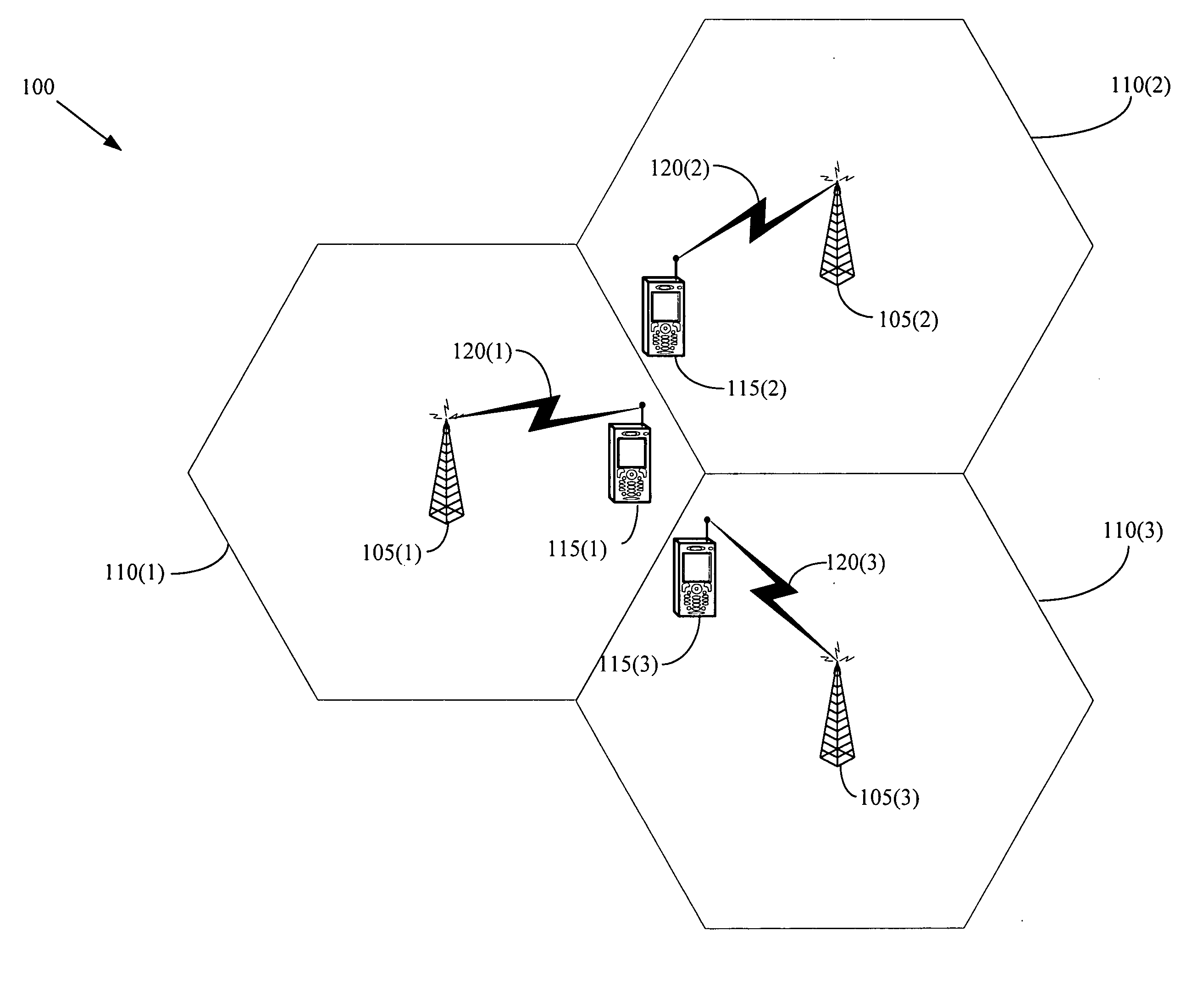
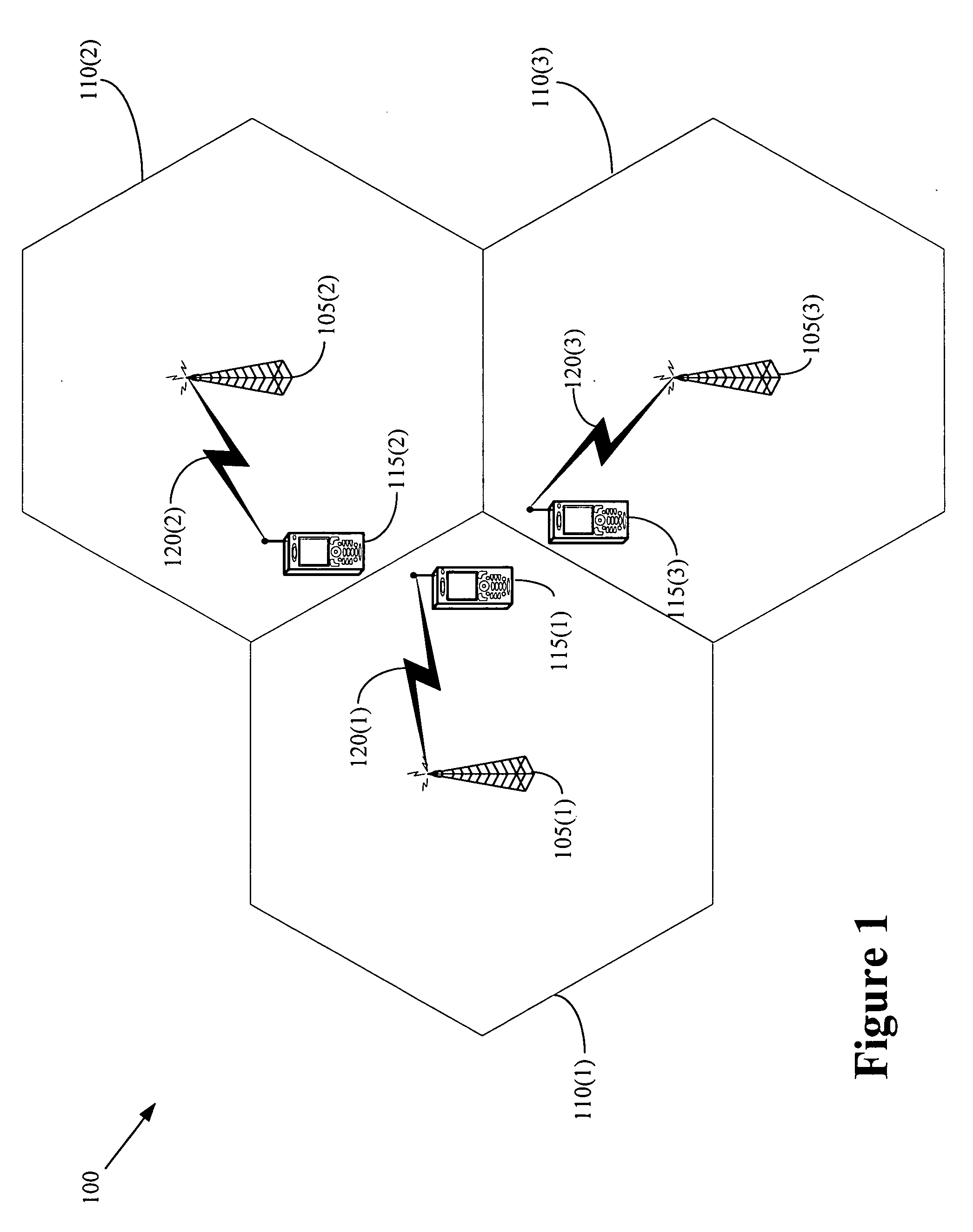
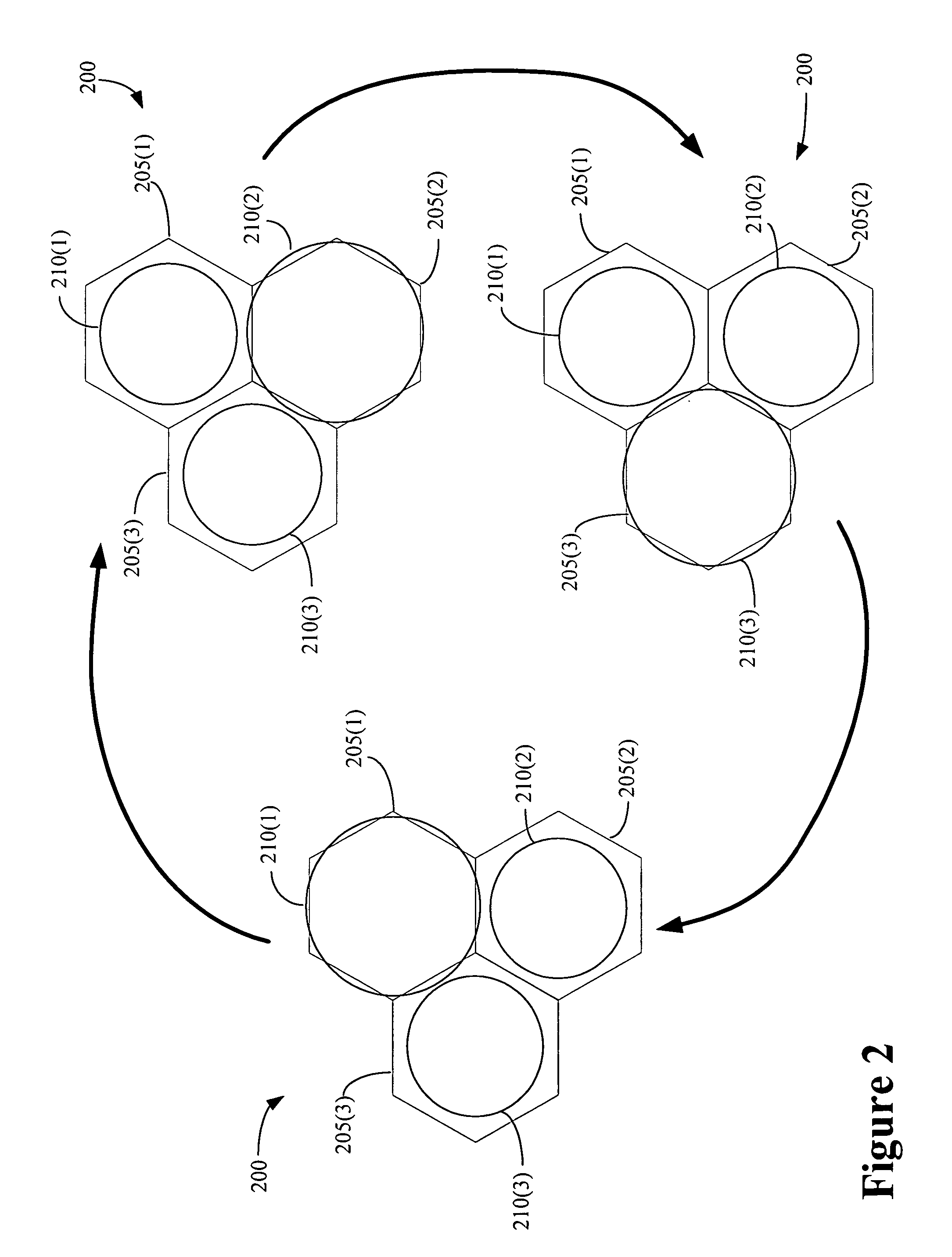
[0008] In one embodiment of the present invention, a method is provided for interference mitigation in a wireless communication system. The method that may include reducing transmission power associated with at least one first channel provided by at least one first base station associated with at least one corresponding first coverage area adjacent a second coverage area associated with a second base station concurrently with maintaining at least one transmission power associated with the second base station(s). The method may also include increasing the transmission power associated with the first channel(s) provided by the first base station(s) concurrently with reducing at least one transmission power associated with at least one first channel provided by the second base station(s).

Problems solved by technology

The noise received by the mobile units includes thermal noise and interference from transmissions associated with other mobile units and / or base stations.
However, interference from transmissions associated with mobile units in adjacent cells may be significant, at least in part because the downlink radio channels used by base stations that serve adjacent cells are not typically orthogonal.
Thus, mobile units near the cell edge are likely to experience the largest degradation in the signal-to-noise ratio.
However, reducing the average power per channel is equivalent to shrinking the overall cell coverage associated with the base station.
However, reducing the number of radio channels is equivalent to reducing the overall system capacity.

Method used


Image

  • Interference mitigation in a wireless communication system
  • Interference mitigation in a wireless communication system
  • Interference mitigation in a wireless communication system

Examples


Embodiment Construction

[0016] Illustrative embodiments of the invention are described below. In the interest of clarity, not all features of an actual implementation are described in this specification. It will of course be appreciated that in the development of any such actual embodiment, numerous implementation-specific decisions should be made to achieve the developers' specific goals, such as compliance with system-related and business-related constraints, which will vary from one implementation to another. Moreover, it will be appreciated that such a development effort might be complex and time-consuming, but would nevertheless be a routine undertaking for those of ordinary skill in the art having the benefit of this disclosure.

[0017] Portions of the present invention and corresponding detailed description are presented in terms of software, or algorithms and symbolic representations of operations on data bits within a computer memory. These descriptions and representations are the ones by which tho...


PUM


Abstract

The present invention provides a method of interference mitigation in a wireless communication system. The method that may include reducing transmission power associated with at least one first channel provided by at least one first base station associated with at least one corresponding first coverage area adjacent a second coverage area associated with a second base station concurrently with maintaining at least one transmission power associated with the second base station(s). The method may also include increasing the transmission power associated with the first channel(s) provided by the first base station(s) concurrently with reducing at least one transmission power associated with at least one first channel provided by the second base station(s).

Description

BACKGROUND OF THE INVENTION [0001] 1. Field of the Invention [0002] This invention relates generally to communication systems, and, more particularly, to wireless communication systems. [0003] 2. Description of the Related Art [0004] The coverage area of a wireless communication system is typically divided into a number of cells, which may be grouped into one or more networks. A base station (or alternatively a node-B, base station router, or access network) typically provides wireless connectivity to mobile units located in each cell. The mobile units may include devices such as mobile telephones, personal data assistants, smart phones, text messaging devices, Global Positioning System devices, wireless network interface cards, desktop or laptop computers, and the like. Mobile units located in each cell may access the wireless communications system by establishing a wireless communication link, often referred to as an air interface, with the base station that serves the cell. [0005...

Claims


Application Information

Patent Timeline
IPC IPC(8): H04B7/00H04Q7/20H04W16/04H04W52/40
CPCH04W16/04Y02B60/50H04W52/40
Inventor CHENG, FANG-CHENSONG, LEILI, SHUPENG
Owner WSOU INVESTMENTS LLC
Learn More