Sentry robot

Inactive Publication Date: 2007-09-06
SAMSUNG TECHWIN CO LTD
View PDF14 Cites 20 Cited by
  • Summary
  • Abstract
  • Description
  • Claims
  • Application Information

AI Technical Summary

Benefits of technology

[0010]To solve the above and/or other problems, the present invention provides a monitoring and sentry robot whi

Problems solved by technology

However, the shooting control system has a problem in that the range of monitoring by a camera device of the system is limited.
Also, the conventional monitoring and sentry system employing a sing

Method used


Image

  • Sentry robot
  • Sentry robot
  • Sentry robot

Examples


Embodiment Construction

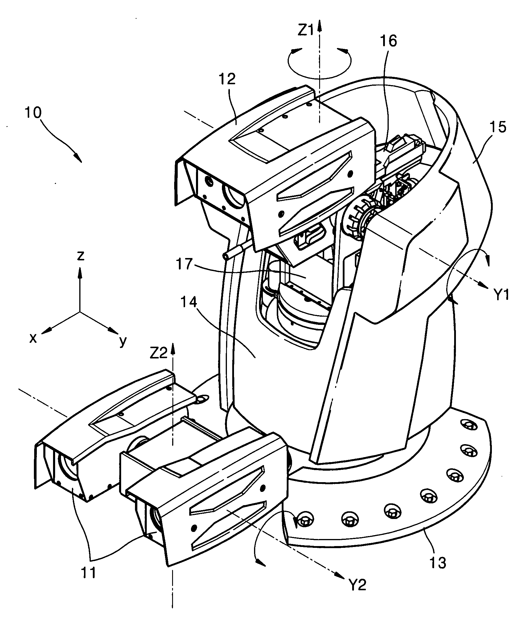
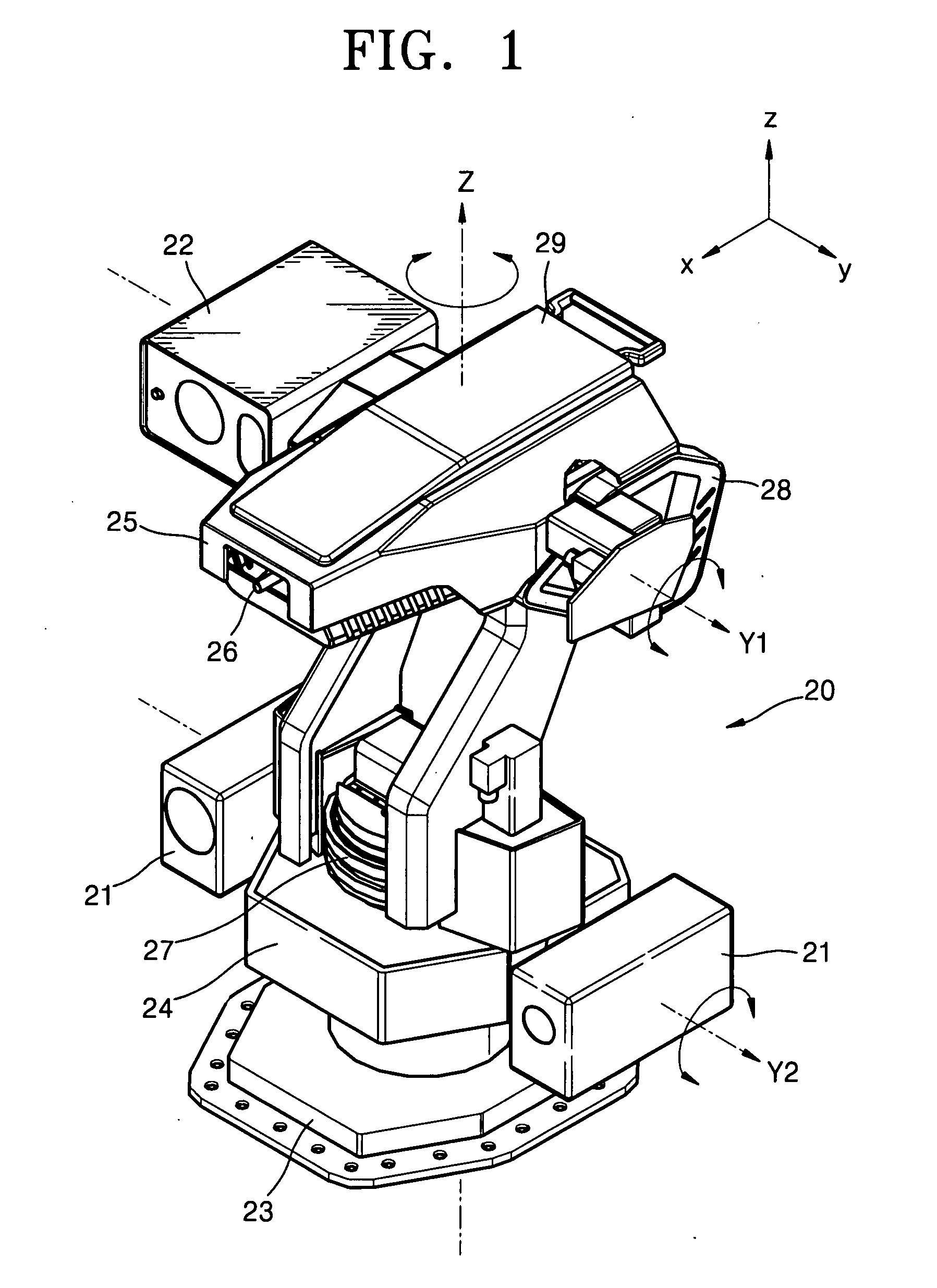
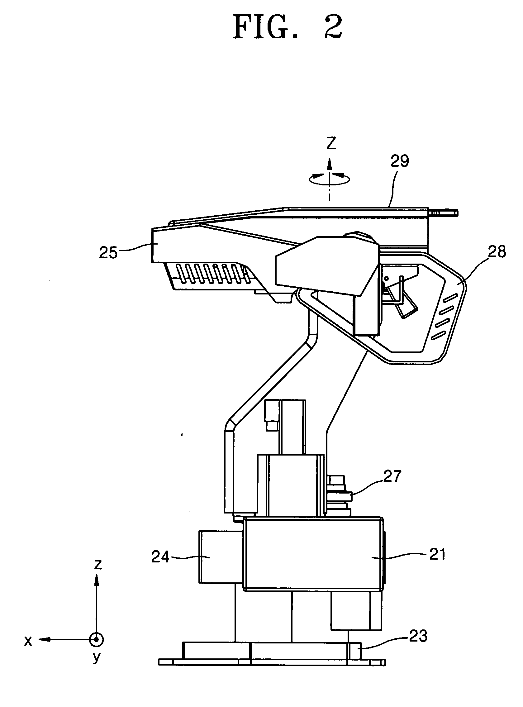
[0025]Referring to FIGS. 1 and 2, a sentry robot 20 according to an embodiment of the present invention includes a base 23, an image monitoring portion, and an image tracking portion.

[0026]The base 23 is a member for fixedly installing the sentry robot 20 at a particular position or to a device. The image monitoring portion includes a main body 24 arranged on the base 23, a master camera 21 and an image monitoring portion driving portion. The image monitoring portion driving mechanism will be described in detail later. The image tracking portion includes an active camera 22 arranged on the main body 24, a gun 26, and an image tracking portion driving mechanism 27.

[0027]The sentry robot 20 is operated by two types of cameras, that is, the master camera 21 and the active camera 22. The sentry robot 20 receives information on the movement of a target from each of the cameras and performs tracking for monitoring and sentry so that a tracking rate and a recognition rate are improved.

[002...


PUM


Abstract

A monitoring and sentry robot which can perform wide and narrow monitoring in short and long ranges and can automatically shoot at a target. The sentry robot includes a base, a main body installed on the base capable of pivoting, a master camera capable of rotating with the main body, and an active camera arranged on the main body capable of rotating in left and right directions and up and down directions with respect to the main body.

Description

CROSS-REFERENCE TO RELATED PATENT APPLICATIONS[0001]This application claims the benefit of Korean Patent Application No. 10-2006-0020409, filed on Mar. 3, 2006, in the Korean Intellectual Property Office, the disclosure of which is incorporated herein in its entirety by reference.BACKGROUND OF THE INVENTION[0002]1. Field of the Invention[0003]The present invention relates to a sentry robot, and more particularly, to a sentry robot capable of performing wide and narrow monitoring in short and long ranges and automatically shooting at a target.[0004]2. Description of the Related Art[0005]Intelligent robot technology is one of the next generation new technologies which will lead the 21st century's industrial and military science technologies with the technical development of artificial intelligence (AI). In particular, a monitoring and sentry system is a sophisticated system employing a variety of technologies such as ultra-low brightness camera technology, image recognition technology...

Claims


Application Information

Patent Timeline
IPC IPC(8): G06F19/00
CPCF41A23/24B25J11/002B25J19/04
Inventor CHOI, KEUN-KUG
Owner SAMSUNG TECHWIN CO LTD
Why Eureka
Try Eureka