Three-eye depth obtaining camera with adjustable optical axes

An adjustable camera technology, applied in image communication, electrical components, stereo systems, etc., can solve the problems of low resolution, affecting the quality of imaging and ranging, and failing to meet the viewing angle requirements, so as to improve efficiency and improve measurement accuracy. Effect

Inactive Publication Date: 2017-09-08
ZHEJIANG UNIV
View PDF8 Cites 5 Cited by
  • Summary
  • Abstract
  • Description
  • Claims
  • Application Information

AI Technical Summary

Problems solved by technology

There are defects in this method of parallel optical axes, because in some scenes, there are requirements for the viewing angle width of the binocular camera, and the parallel optical axis can only fix the viewing angle of the optical axis, so that the requirements for the viewing angle cannot be met
[0003] In addition, when the parallel optical axis recognizes cylindrical objects, the information obtained is less than that of the adjustable (adjusted to acute angle) optical axis, and it is also less than the information obtained by three or more cameras, which ultimately affects the quality of imaging and ranging
At the same time, the binocular camera based on epipolar geometry limits the number of cameras, and it is necessary to find a way to use additional cameras
The TOF ranging camera can directly obtain the distance information cloud image, but its disadvantage is that the resolution is too low

Method used


Image

  • Three-eye depth obtaining camera with adjustable optical axes
  • Three-eye depth obtaining camera with adjustable optical axes
  • Three-eye depth obtaining camera with adjustable optical axes

Examples


Embodiment 1

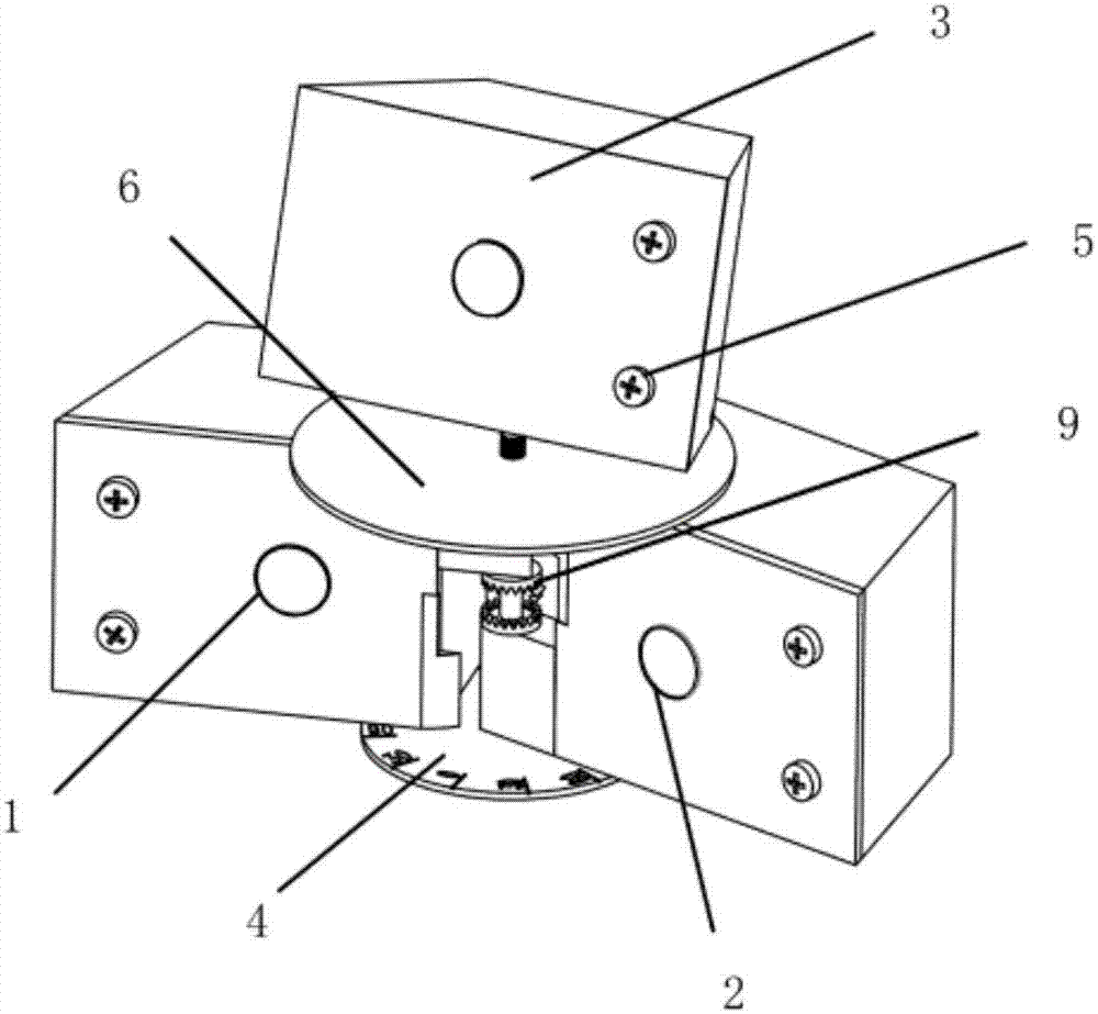
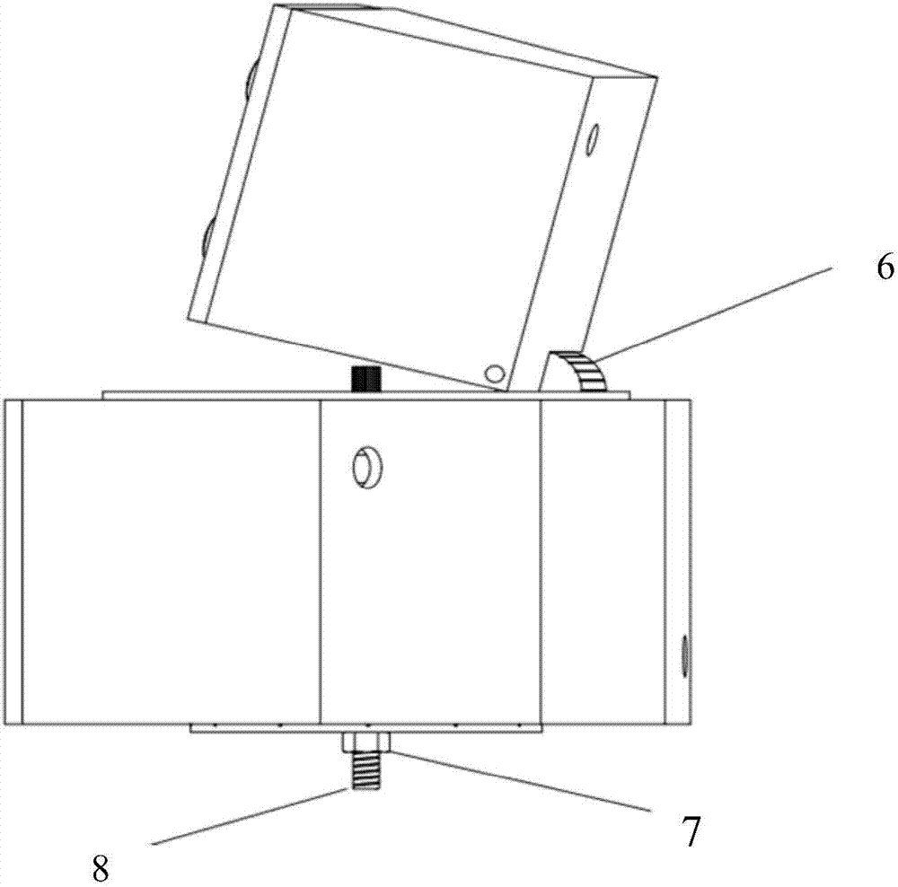
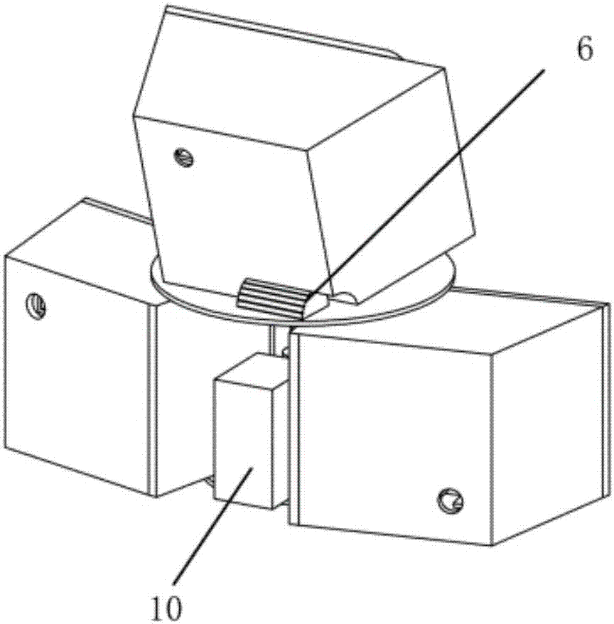
[0036] The optical axis adjustable trinocular depth acquisition camera includes a left camera 1 , a right camera 2 and an upper active camera 3 . Such as figure 1 , 2 , 3, the left camera 1 and the right camera 2 are matched through 8 shaft holes of the threaded rod, and then tightened with the nut 7 to fix the angle of the binocular camera, and the angle can be read with the code disc 4. The pitch angle and rotation angle of the upper active camera 3 can also be read out through the corresponding code disc. The left and right cameras are ordinary imaging cameras, which do not have the function of active depth acquisition, and their depth measurement is obtained through digital image processing technology. The upper camera uses an active depth camera, such as a TOF camera, to directly obtain a depth cloud image with low precision. Each camera is connected to the host computer respectively.

[0037] Such as Figure 5 Shown, threaded rod 8 upper ends adopt frictional design...

Embodiment 2

[0040] according to Figure 8 In the flow chart shown, depth information is acquired through the processes of angle adjustment S11 , photographing acquisition S12 , stereo matching S13 and depth calculation S14 . Among them, the stereo matching algorithm marks the pixel points (blocks) where the left camera 1 and the right camera 2 match each other, and a local stereo matching algorithm can be selected, specifically:

[0041] 1. Construct a small window, similar to a convolution kernel.

[0042] 2. Use the window to cover the image on the left, and select all the pixels in the area covered by the window.

[0043] 3. Also use the window to cover the image on the right and select the pixels in the covered area.

[0044] 4. Subtract the right coverage area from the left coverage area, and calculate the sum of the absolute values ​​of all pixel point differences.

[0045] 5. Move the window of the image on the right, and repeat steps 3 and 4. (There is a search range here, jum...

Embodiment 3

[0050] Such as Figure 7 Shown is the schematic diagram of non-parallel optical axes.

[0051] According to the relevant principles of epipolar geometry, the vertical distance from the point P to the origin O can be obtained by means of plane geometry. The coordinate system is established as shown in the figure, and the equations of the two incident rays can be obtained:

[0052]

[0053]

[0054] in is the angle between the left and right cameras and the direction facing the world coordinates, in this embodiment T is the distance from the main optical axis of the camera to the rotation point, f is the focal length of the left and right cameras, and x is the coordinate of the image coordinate system of the left and right cameras. x L is the coordinate of the left camera image coordinate system, x R is the coordinate of the right camera image coordinate system.

[0055] Simultaneously, the value of distance Z can be obtained as:

[0056]

[0057] Thus, the dista...


PUM


Abstract

The invention discloses a trinocular depth acquisition camera with adjustable optical axis. Two independent camera modules are arranged on the left and right sides, and an active depth camera is arranged on the top. Drive synchronous rotation, and automatically output the angle. The left and right cameras are matched through a threaded shaft hole, and another code disc is used to indicate the angle between the two optical axes. In the present invention, the non-parallel optical axis is used in the calculation of the depth information, and the angle of view in the acquisition of the depth information becomes a value that can be adjusted according to the actual situation by setting the form of the adjustable optical axis. And by adding an active depth camera, the binocular ranging information is combined with the active depth camera ranging information, so that the final depth data can be better reflected.

Description

technical field [0001] The invention relates to the field of depth cameras, and relates to a trinocular depth acquisition camera with an adjustable optical axis. Background technique [0002] In the current field of depth cameras, there are two types: active depth cameras and passive depth cameras. In the field of passive depth cameras, existing binocular or multi-eye depth cameras often work in a manner of parallel optical axes, and use parallel optical axes to perform plane geometry calculations. There are defects in this way of paralleling the optical axis, because in some scenes there are requirements for the viewing angle width of the binocular camera, and the parallel optical axis can only fix the viewing angle of the optical axis, so that the requirements for the viewing angle cannot be met. [0003] In addition, when the parallel optical axis recognizes cylindrical objects, the information obtained is less than that of the adjustable (adjusted to acute angle) optica...

Claims


Application Information

Patent Timeline
Patent Type & Authority Applications(China)
IPC IPC(8): H04N13/00H04N13/02
Inventor 王宣银蒋雪松向可
Owner ZHEJIANG UNIV
Why Eureka
Try Eureka