Method And Apparatus For Storing Heat Energy

a technology of heat energy and storage method, applied in the field of energy storage, can solve the problems of limited application, inability to store easily for extended periods of time, and inability to pump heat at elevated temperatures, so as to reduce the requirement of structural strength and increase the structural strength of the chamber or enclosure.

Active Publication Date: 2007-09-13
GRAPHITE ENERGY ASSETS PTY LTD
View PDF7 Cites 58 Cited by
  • Summary
  • Abstract
  • Description
  • Claims
  • Application Information

AI Technical Summary

Benefits of technology

The patent text discusses the optimal pressure for an operating system. The text explains that a pressure of 5 to 15 milli-bar is needed to prevent corona discharge, but a pressure of 900 micro-bar or higher is needed to ensure structural strength. To maintain the optimal pressure, the system should maintain the pressure just over atmospheric pressure, which is preferably non-combustible or inert in nature to minimize the ingress of oxygen. The technical effect of this patent text is to provide a solution for maintaining optimal pressure in a thermal storage chamber or enclosure to prevent corona discharge and ensure structural strength.

Problems solved by technology

The technical problem addressed in this patent text is the need for a system to store and utilize heat energy in a cost-effective and efficient manner, as well as the need for better integration of renewable energies into power grids. Additionally, there is a need for a method and apparatus for storing heat energy at high temperatures.

Method used


Image

  • Method And Apparatus For Storing Heat Energy
  • Method And Apparatus For Storing Heat Energy
  • Method And Apparatus For Storing Heat Energy

Examples


Embodiment Construction

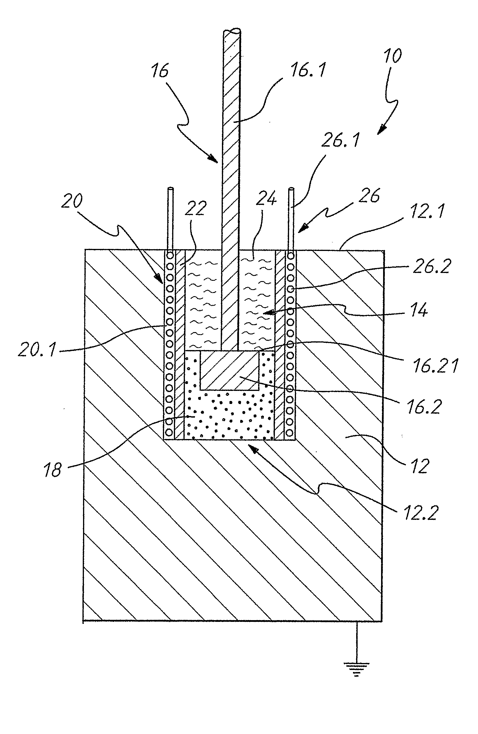
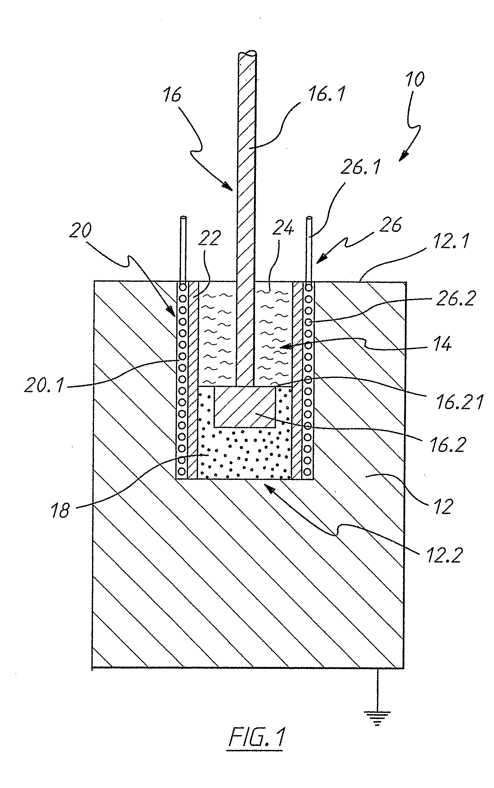
[0191] Referring to FIG. 1, there is shown one embodiment of an apparatus 10 for storing heat energy. The apparatus 10 comprises a body 12 of high purity graphite containing less than 0.5% by weight of impurities. The apparatus 10 further comprises means 14 for transferring heat to the body 12, the means 14 comprising an electrode 16 and a resistor 18. The resistor 18 is located inside the bore or well 20 which extends from the top surface of 12.1 of the body 12, to a point 12.2 within the body 12 which is remote from the surface thereof.

[0192] A ceramic tube 22 fits into the bore or well 20. Its diameter is, however, smaller than that of the bore or well 20, leaving an annular space 20.1 between the outer surface of the tube 22 and the inner surface of the bore or well 20.

[0193] The electrode 16 comprises a stem portion 16.1 and a base portion 16.2. The base portion 16.2 is embedded inside a mixture of granular graphite or carbon and with or without ceramic granules which constit...


PUM


Abstract

A method of and an apparatus for storing heat energy in a body of graphite at an elevated temperature are disclosed. The method comprises heating an inner region of a body of graphite when it is required to store the heat energy and recovering the heat by way of a heat exchanger, when the energy is required to be used. The apparatus is suitable for the storage of renewable energy and electric energy obtainable from off peak periods of supply.

Description


Claims


Application Information

Patent Timeline
Owner GRAPHITE ENERGY ASSETS PTY LTD
Why Eureka
Try Eureka