
Wind power equipment and electrostatic dust collection device thereof

A technology of electrostatic dust removal and wind power equipment, applied in the field of air purification, which can solve the problems of reducing the flow area of ​​the air duct, large air pressure loss, and complicated manufacturing process, and achieves good dust removal effect, reduced pressure loss, and simple manufacturing process.

Pending Publication Date: 2020-08-04
SHUNDE APOLLO AIR CLEANER
View PDF4 Cites 0 Cited by
  • Summary
  • Abstract
  • Description
  • Claims
  • Application Information

AI Technical Summary

Problems solved by technology

[0004] 1. The production process is complicated, and the entire surface of the conductive material needs to be covered with a plastic wall, which leads to low production efficiency and high production costs;
[0005] 2. There is usually a supporting wall between any adjacent two plastic walls to ensure that the plastic wall will not be deformed, and the setting of the supporting wall will reduce the flow area of ​​the air duct, resulting in a large loss of airflow pressure, thereby reducing dust collection. s efficiency

Method used


Image

  • Wind power equipment and electrostatic dust collection device thereof
  • Wind power equipment and electrostatic dust collection device thereof
  • Wind power equipment and electrostatic dust collection device thereof

Examples


Embodiment 1

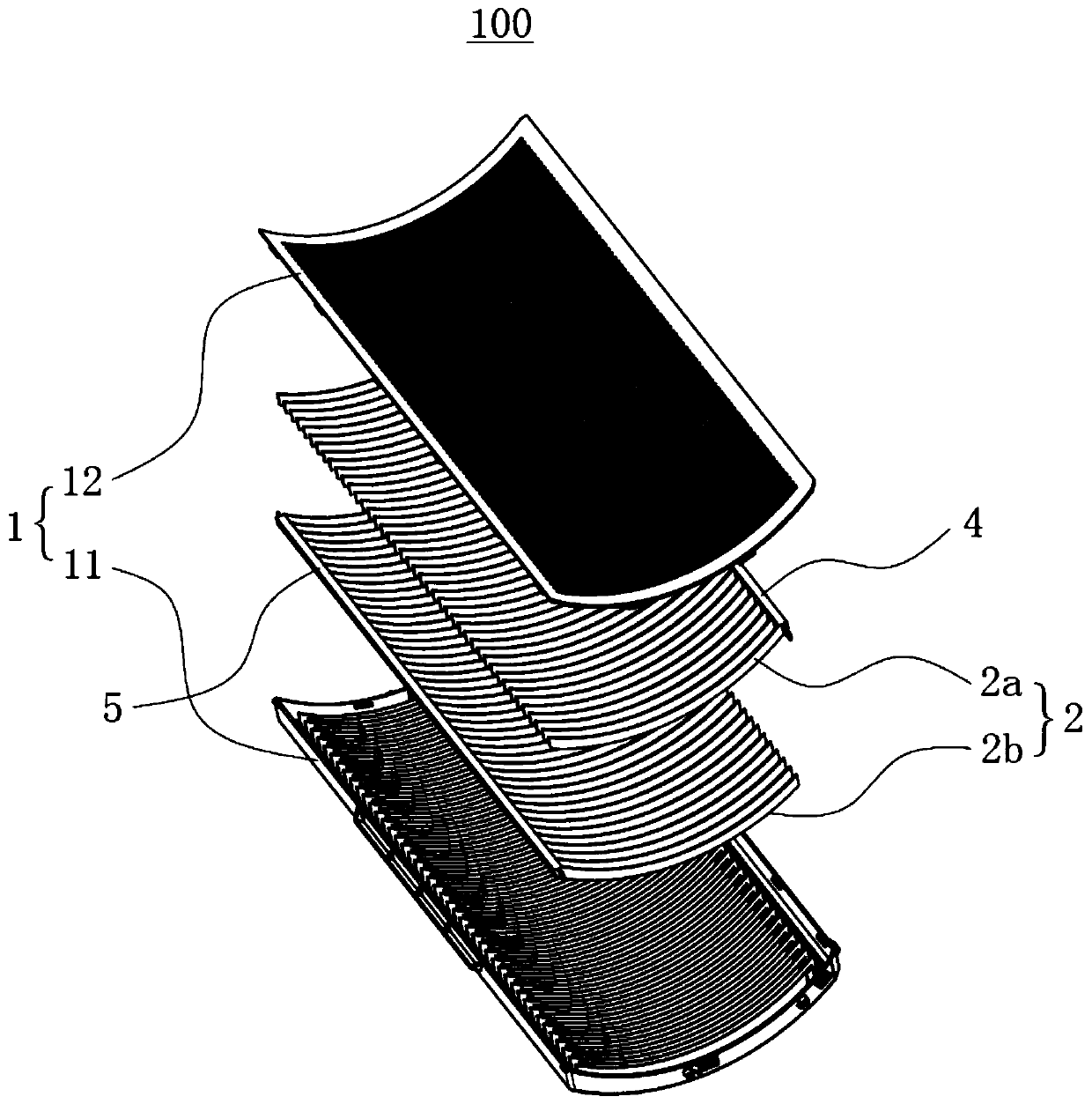
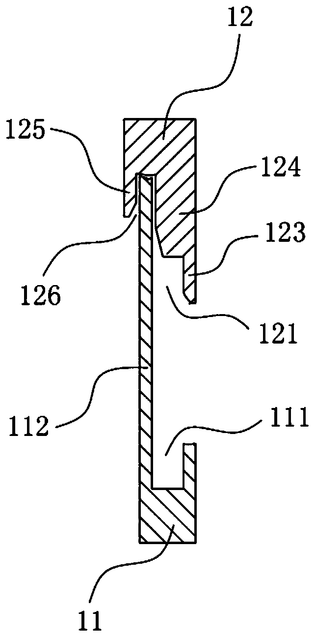
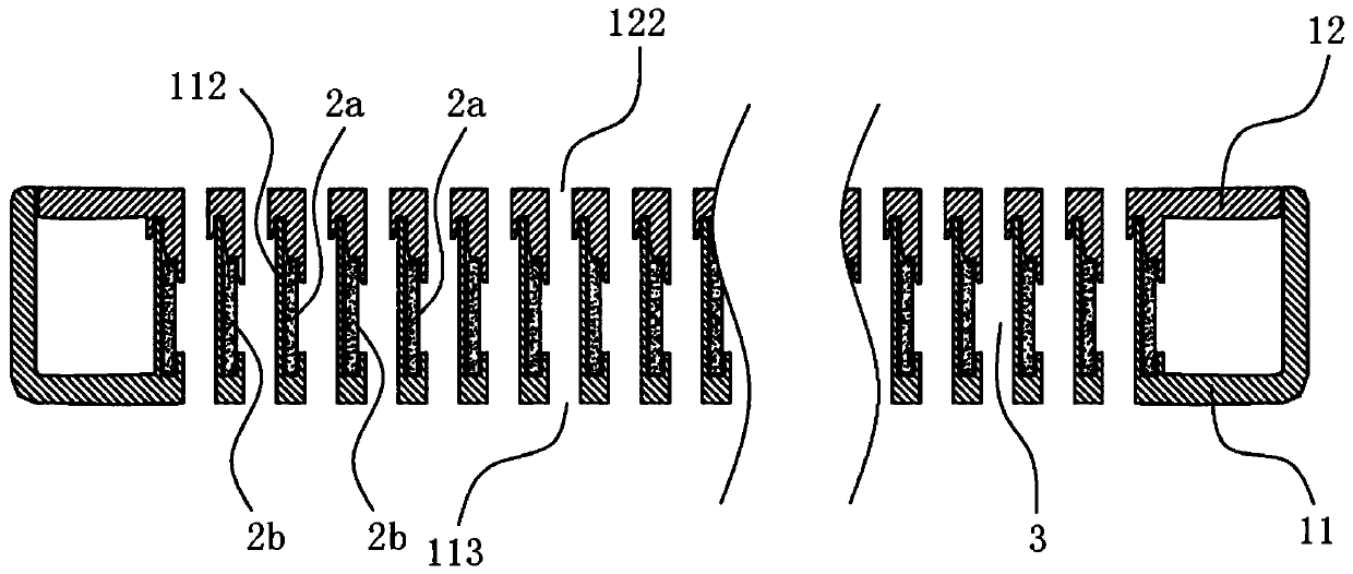
[0043] combine Figure 1 to Figure 3As shown, the embodiment of the present invention provides an electrostatic precipitator 100, which mainly includes a casing 1 and a potential plate 2 arranged in the casing 1; the casing 1 includes a first casing plate 11 and a second casing plate 12 arranged oppositely. , the surface of the first shell plate 11 facing the second shell plate 12 is provided with a first installation groove 111 , and the surface of the second shell plate 12 facing the first shell plate 11 is provided with a second installation groove corresponding to the first installation groove 111 121, the two sides of the potential plate 2 are respectively inserted into the first installation slot 111 and the second installation slot 121; the potential plate 2 is used to form an electric field, which is set to at least two pieces, and at least one of the potential plates 2 is used for connecting The positive pole of the power supply is denoted as high potential plate 2a, ...

Embodiment 2

[0059] like Figure 10 As shown, the difference between this embodiment and the first embodiment is that the insulating structure is an insulating coating 118 having a certain thickness, and the insulating coating 118 is provided on one surface of the potential plate 2 . Correspondingly, refer to image 3 It can be seen that the second shell 12 is no longer provided with the first slats 123, the second slats 125 and the third installation grooves 126, and the second installation grooves 121 are no longer composed of the first slats 123 and the insulating structure, but are replaced by What is fixed is the second installation groove 121 fixed on the second shell plate 12 . Except for the above differences, other specific structures of the embodiment of the present invention are the same as those in the first embodiment, and the corresponding principles and technical effects are also the same, which will not be repeated here.

[0060] To sum up, the present invention provides ...


PUM


Abstract

The invention provides an electrostatic dust collection device. A potential plate is used as a conductive material, and a mounting groove and an air port are formed in a housing plate and used for fixing the potential plate and forming an air duct, so that on one hand, the structure of the whole electrostatic dust collection device is simplified, and on the other hand, the circulation area of theair duct is ensured, the pressure loss when airflow passes through the air duct is reduced, and the dust collection efficiency is improved; and secondly, an insulating structure arranged between a high-potential plate and a low-potential plate can effectively prevent corona discharge in the air duct, so that the generation of ozone and the occurrence of electric shock accidents are avoided, and the safety of the electrostatic dust collection device is improved. Therefore, compared with an existing electrostatic dust collection device, the electrostatic dust collection device provided by the invention is simpler in manufacturing process, higher in production efficiency, lower in production cost and better in dust collection effect. The invention further provides wind power equipment adopting the electrostatic dust collection device. The wind power equipment has the advantages of being capable of collecting dust, easy to assemble, low in energy consumption, large in air volume and the like.

Description

technical field [0001] The invention relates to the technical field of air purification, in particular to a wind power equipment and an electrostatic precipitator thereof. Background technique [0002] Electrostatic precipitator is a kind of gas dedusting method. Its principle is: when the dust-containing gas passes through a high-voltage electrostatic field, it is electrically separated, and after the dust particles and negative ions are negatively charged, they tend to discharge and deposit on the surface of the anode. That is, in the strong electric field, the air molecules are ionized into positive ions and electrons, and the electrons encounter dust particles in the process of running to the positive electrode, so that the dust particles are negatively charged and adsorbed to the positive electrode to be collected. Electrostatic dust removal technology is widely used in metallurgy, mining, chemical, pharmaceutical, power generation, smelting and other industries to puri...

Claims


Application Information

Patent Timeline
Patent Type & Authority Applications(China)
IPC IPC(8): B03C3/08B03C3/47F04D29/70
CPCB03C3/08B03C3/47F04D29/703
Inventor 方齐皮小春吴孝乐孟健何健彬
Owner SHUNDE APOLLO AIR CLEANER
Learn More