
Method for manufacturing float glass and device therefor

a technology of float glass and manufacturing method, which is applied in the direction of glass making apparatus, glass rolling apparatus, manufacturing tools, etc., can solve the problems of glass surface undulation, and achieve the effect of stable thickness, stable flatness, and stable holding in the recessed portions

Inactive Publication Date: 2007-09-13
ASAHI GLASS CO LTD
View PDF4 Cites 4 Cited by
  • Summary
  • Abstract
  • Description
  • Claims
  • Application Information

AI Technical Summary

Benefits of technology

The present invention relates to a method and device for manufacturing flat glass using the float process. The invention addresses the problem of undulations on the glass surface caused by the top rollers used in conventional devices. The invention proposes a method and device that holds both edges of the molten glass ribbon in a way that prevents the edges from narrowing or spreading in the width direction. This results in a smaller thickness of the flat glass manufactured. The invention also addresses the problem of uneven temperature distribution along the molten glass ribbon caused by the flow rate of the molten tin. The invention proposes a method and device that achieves a more stable and uniform shape of the recessed portion of the bath surface and a more stable temperature distribution.

Problems solved by technology

The device for manufacturing flat glass by use of such top rollers has a problem in that undulations are caused on a glass surface during the stretching operation by the top rollers.

Method used


Image

  • Method for manufacturing float glass and device therefor
  • Method for manufacturing float glass and device therefor
  • Method for manufacturing float glass and device therefor

Examples


Embodiment Construction

[0025] Now, the method for manufacturing float glass and a device therefor, according to a preferred embodiment of the present invention will be described in detail, referring to the accompanying drawings.

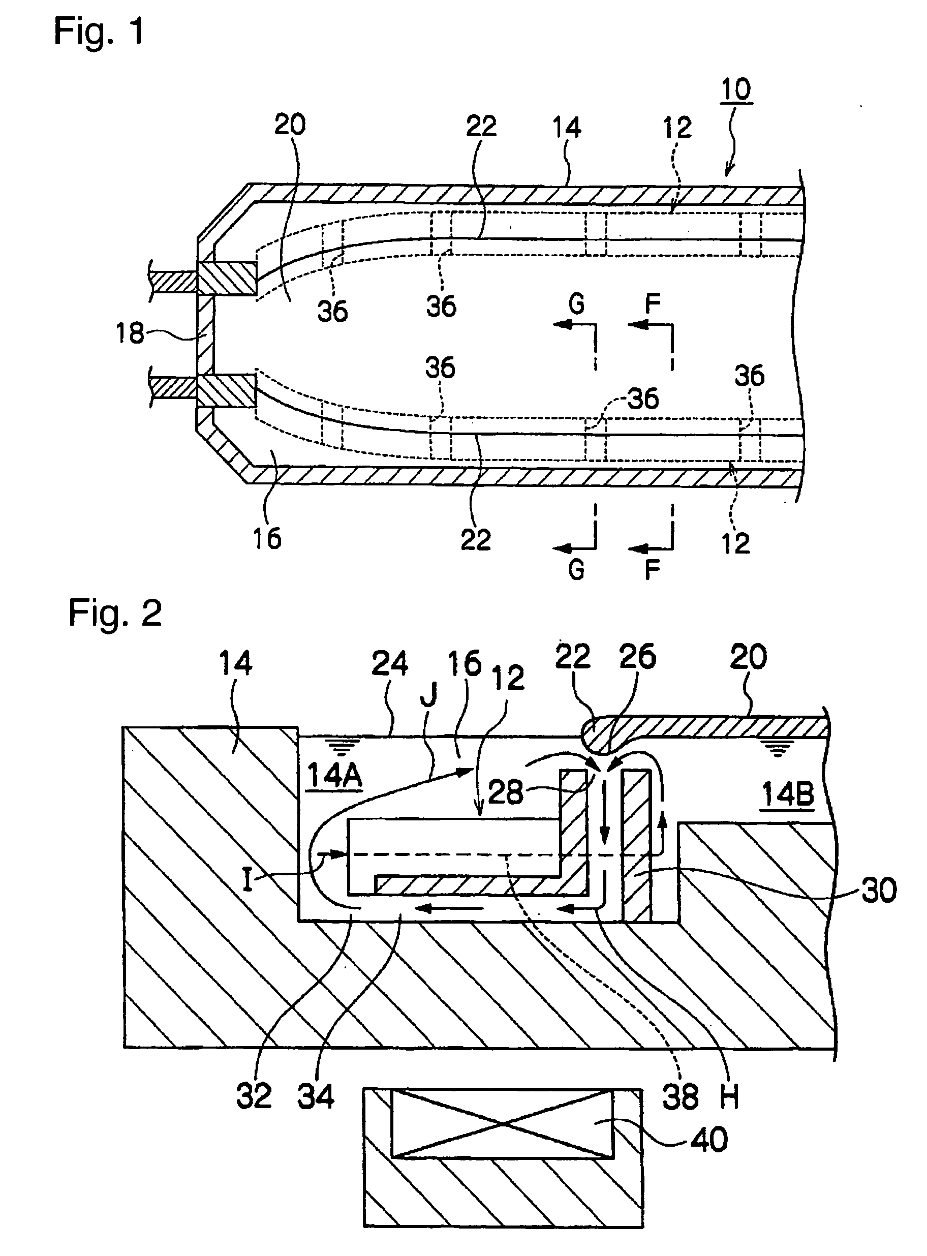
[0026]FIG. 1 is a plan view showing the device 10 for manufacturing float glass, which manufactures flat glass for an FPD (Flat Panel Display), in particular a liquid crystal display and the like. The flat glass for an FPD, such as a liquid crystal display, is generally required to have a thickness of from about 0.3 to 1.0 mm and is also required to have a flatness with a high degree of accuracy. The device 10 for manufacturing float glass by use of gutter-like bodies 12 is applied to the device for manufacturing float glass for an FPD. In accordance with the device 10 for manufacturing float glass, it is possible to manufacture flat glass, which satisfies the thickness and the flatness required as flat glass for an FPD.

[0027] The gutter-like bodies 12 of the device 10 for manufa...


PUM

PropertyMeasurementUnit
thicknessaaaaaaaaaa
temperatureaaaaaaaaaa

Abstract

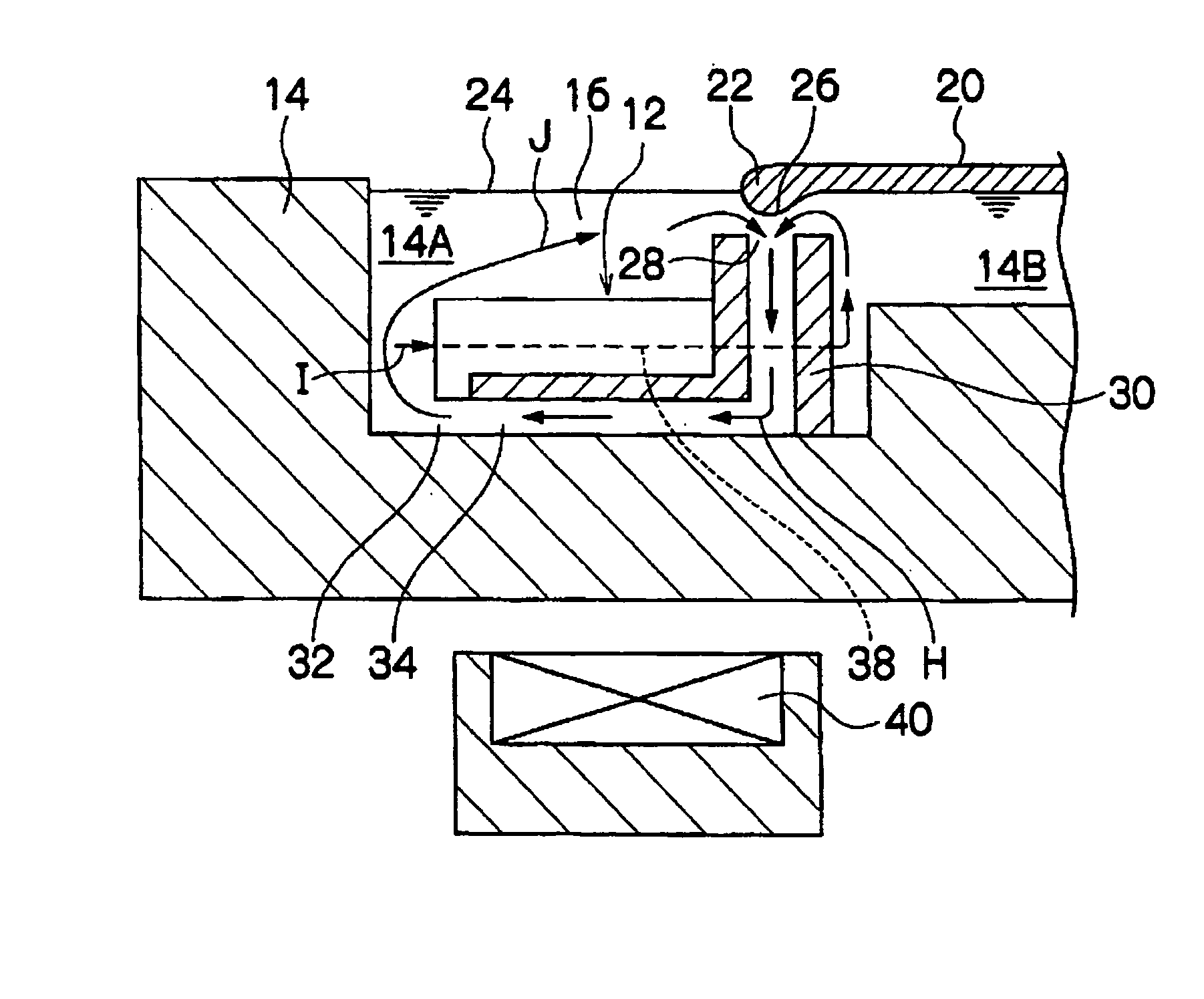
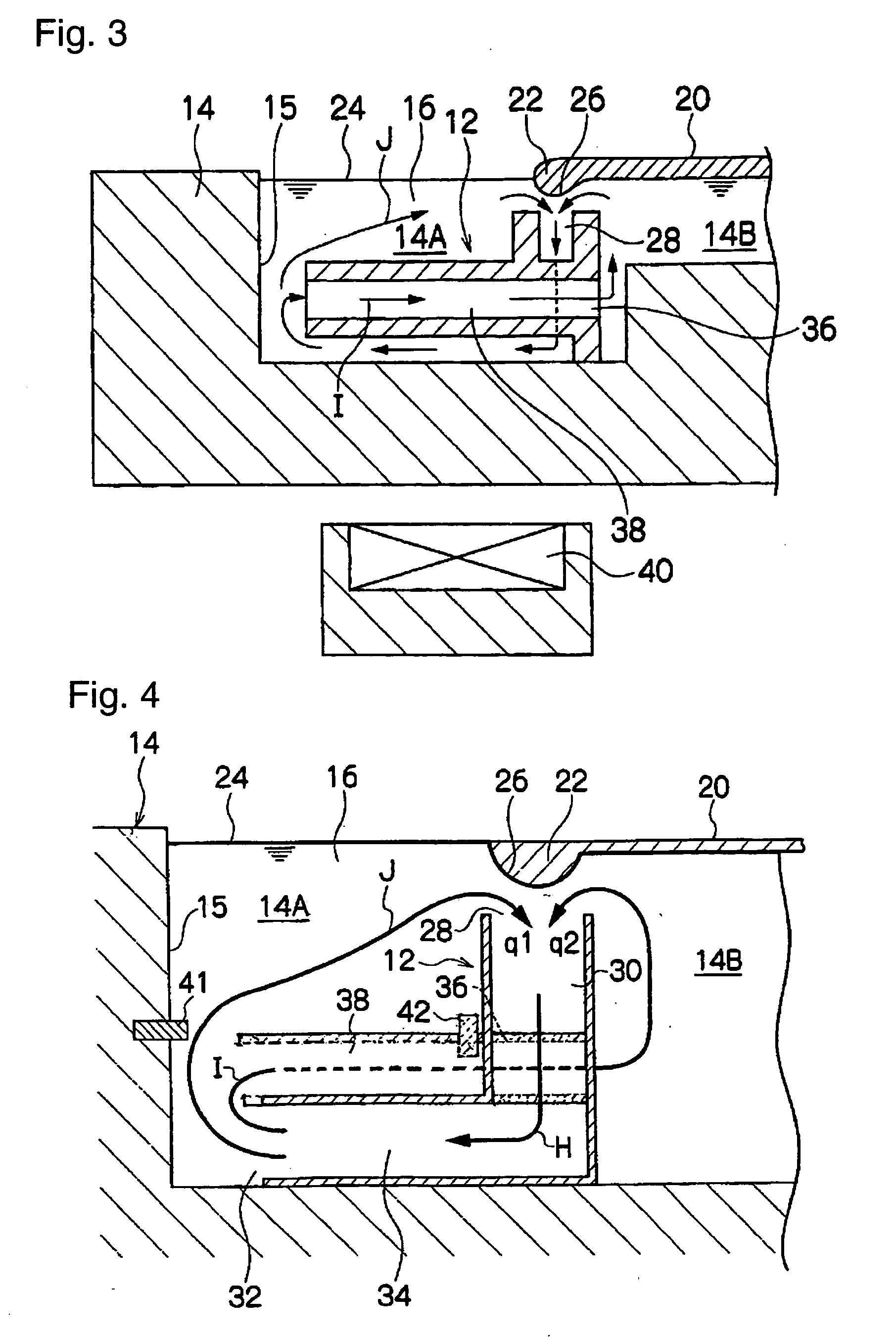
It is an object of the present invention to provide a method for manufacturing float glass and a device therefor, which are capable of stably holding both edges of a molten glass ribbon. In accordance with gutter-like bodies 12 of a device for manufacturing float glass 10, a portion of molten tin 16 that flows out of outlets 32 of lateral ducts 34 of the gutter-like bodies 12 into vessel edge areas 14A can be directed to a vessel central area 14B through vertical ducts 30 and through holes 36. Since the flow rate q1 of the molten tin 16 that flows from each of the vessel edge areas 14A into each of the inlets 28, and the flow rate q2 of the molten tin 16 that flows from the vessel central area 14B into each of the inlets 28 are substantially equalized along the forward direction of the molten glass ribbon 20. Accordingly, recessed portions 26 are substantially uniformly formed on a bath surface 24 in such an appropriate shape to hold the edges along the forward direction of the molten glass ribbon 20, with the result that the edges 22 can be stably held in the recessed portions 26, making it possible to obtain a stable glass quality.

Description

TECHNICAL FIELD [0001] The present invention relates to a method for manufacturing float glass by the float process and a device therefor, which are characterized by holding both edges of a molten glass ribbon supplied on a molten metal bath surface. BACKGROUND ART [0002] A device for manufacturing flat glass by the float process is a device, wherein molten glass is continuously supplied on molten metal, such as molten tin, contained in a vessel, the supplied molten glass is caused to float and move forward on the molten tin, and a glass ribbon comprising the molten glass, which has achieved the equilibrium thickness at that time or is gradually achieving the equilibrium thickness, is pulled toward the outlet of the molten tin bath, i.e., a lehr (downstream annealing zone) disposed adjacent the outlet of the molten tin bath to manufacture flat glass having a certain width. In such a device for manufacturing flat glass by the float process, the molten glass ribbon, which has achieved...

Claims


Application Information

Patent Timeline
Patent Type & Authority Applications(United States)
IPC IPC(8): C03B13/00C03B18/00C03B18/02C03B18/04
CPCC03B18/04C03B18/00
Inventor IGA, MOTOICHIINOUE, ATSUSHIKAKIMOTO, YASUHIROKAMIHORI, TORUTAKIGUCHI, TETSUSHI
Owner ASAHI GLASS CO LTD
Learn More