
Glass tubes for lamps, method for manufacturing the same, and lamps

a technology for glass tubes and lamps, which is applied in the direction of discharge tubes, discharge tubes general techniques, discharge tubes, etc., can solve the problems of shorten and achieve the effect of prolonging the service life of lamps

Inactive Publication Date: 2007-09-13
SEIKO EPSON CORP
View PDF5 Cites 5 Cited by
  • Summary
  • Abstract
  • Description
  • Claims
  • Application Information

AI Technical Summary

Benefits of technology

[0006]In accordance with an advantage of some aspects of the invention, glass tubes for lamps and methods for manufacturing the same, which can extend the service life of the lamps, can be provided. Also, lamps that use the aforementioned glass tubes for lamps can be provided.
[0008]In the glass tube for lamp described above, at least a portion of the inner surface of the glass section in an area that forms the light emission section of the lamp is covered by the ceramics film. As a result, adhesion of impurities to the inner surface of the glass section can be prevented, and the devitrification temperature of the glass section can be prevented from lowering. Accordingly, with the glass tube for lamp described above, the service life of the lamp can be extended.

Problems solved by technology

However, for example, when an electrode material that is thermally evaporated adheres as an impurity to an inner surface of a quartz glass tube of a lamp, the temperature at which devitrification occurs (hereafter referred to as a “devitrification temperature”) may lower, and devitrification of quartz glass of the quartz glass tube may occur at a temperature below 1000° C. The lowered devitrification temperature may shorten the service life of the lamp.

Method used


Image

  • Glass tubes for lamps, method for manufacturing the same, and lamps
  • Glass tubes for lamps, method for manufacturing the same, and lamps
  • Glass tubes for lamps, method for manufacturing the same, and lamps

Examples


Embodiment Construction

[0024]Preferred embodiments of the invention are described below with reference to the accompanying drawings.

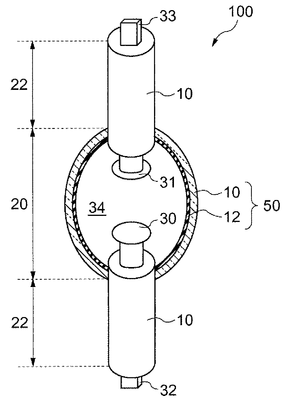
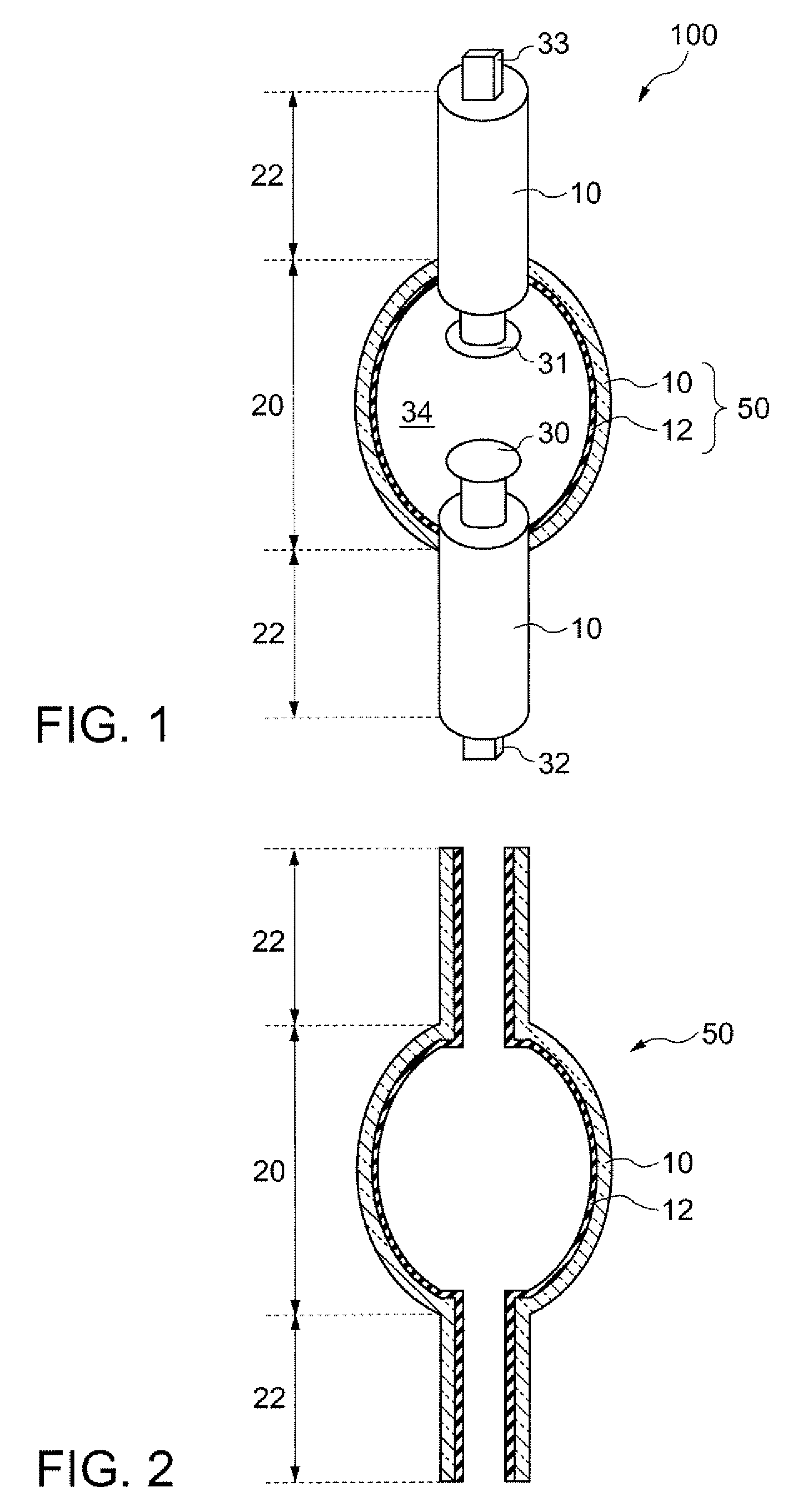
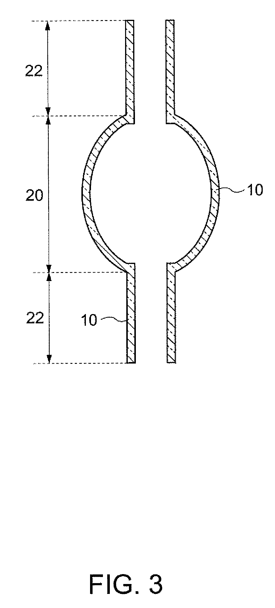
[0025]1. First, a lamp and a glass tube for the lamp in accordance with an embodiment of the invention are described. FIG. 1 is a perspective view schematically showing a lamp 100 in accordance with an embodiment of the invention, with a cross section in part of the lamp 100. FIG. 1 shows a cross section of a glass tube 50 of the lamp in a region that forms a light emission section (hereafter also referred to as a “first area”) 20. FIG. 2 is a cross-sectional view schematically showing the glass tube for lamp in accordance with the present embodiment.

[0026]The lamp 100 may be, for example, a high-pressure mercury vapor lamp. The lamp 100 includes a glass tube for the lamp 50, a first electrode 30, a second electrode 31, a first terminal 32, a second terminal 33, and an internal space 34. The glass tube for lamp 50 includes, as shown in FIG. 2, a glass section 10 and a ceramic...


PUM


Abstract

A glass tube for lamp includes: a tubular glass section having open ends; and a ceramics film that covers at least a portion of an inner surface of the glass section in an area that forms a light emission section of the lamp.

Description

[0001]The entire disclosure of Japanese Patent Application No. 2006-067774, filed Mar. 13, 2006 is expressly incorporated by reference herein.BACKGROUND[0002]1. Technical Field[0003]The present invention relates to glass tubes for lamps and methods for manufacturing the same, and lamps.[0004]2. Related Art[0005]Quartz glass tubes are used as arc tubes of light emitting lamps that may be used for projectors or the like (for example, see JP-A-2005-309372). When quartz glass is exposed to high-temperatures, its glass state (amorphous) transforms to cristobalite (crystalline) state, in other words, devitrification occurs. In the case of quartz glass, devitrification normally occurs at 1150° C. or higher. However, for example, when an electrode material that is thermally evaporated adheres as an impurity to an inner surface of a quartz glass tube of a lamp, the temperature at which devitrification occurs (hereafter referred to as a “devitrification temperature”) may lower, and devitrific...

Claims


Application Information

Patent Timeline
IPC IPC(8): H01J61/30
CPCH01J9/20H01J2209/012H01J61/35
Inventor KIJIMA, TAKESHI
Owner SEIKO EPSON CORP
Learn More