PFM and current controlled switching regulator

a current control and switching regulator technology, applied in the direction of electric variable regulation, process and machine control, instruments, etc., can solve the problems of low efficiency of switching regulators at light load (low output current) conditions

Active Publication Date: 2007-09-13
MICREL
View PDF7 Cites 78 Cited by
  • Summary
  • Abstract
  • Description
  • Claims
  • Application Information

AI Technical Summary

Benefits of technology

[0010] According to one embodiment of the present invention, a circuit for controlling a switching regulator includes an error amplifier, a first, second and third control circuits. The switching regulator receives an input voltage and includes a switch circuit coupled to generate a switching output voltage and an output circuit coupled to receive the switching output voltage and to supply current at a regulated output voltage to a load. The error amplifier has a first input node coupled to receive a first voltage indicative of the regulated output voltage, a second input node coupled to receive a reference voltage and an output node providing an error voltage responsive to the difference between the first voltage and the reference voltage.

Problems solved by technology

A problem faced by most types of switching regulators is maintaining high efficiency at light load conditions.
Switch regulators typically become very inefficient at light load (low output current) conditions.
The efficiency of a switching regulator is limited by several factors, such as losses that are proportional to the output power, fixed losses for each switching cycle, and losses which are constant independent of the voltage conversion process (e.g. quiescent supply current of the control circuit).
The conventional solutions to maintaining efficiency at light load conditions are dissatisfactory for several reasons.
First, the PFM technique is problematic if a very wide range of powers is expected.
In most applications, it is disadvantageous to allow the switching frequency to modulate down into the audio range, and it is also desirable to prevent the high switching frequency to exceed more than a couple Megahertz.
Thus, the PFM technique only provides two orders of magnitude range over which modulation should occur.
The frequency range limitation makes the PFM technique not practical for all applications.
A main disadvantage of the burst mode slow response time.
If the load steps from low to high power demand, the switching regulator may not respond in a timely manner if the load changes occur during when the switching regulator is turned off.

Method used


Image

  • PFM and current controlled switching regulator
  • PFM and current controlled switching regulator
  • PFM and current controlled switching regulator

Examples


Embodiment Construction

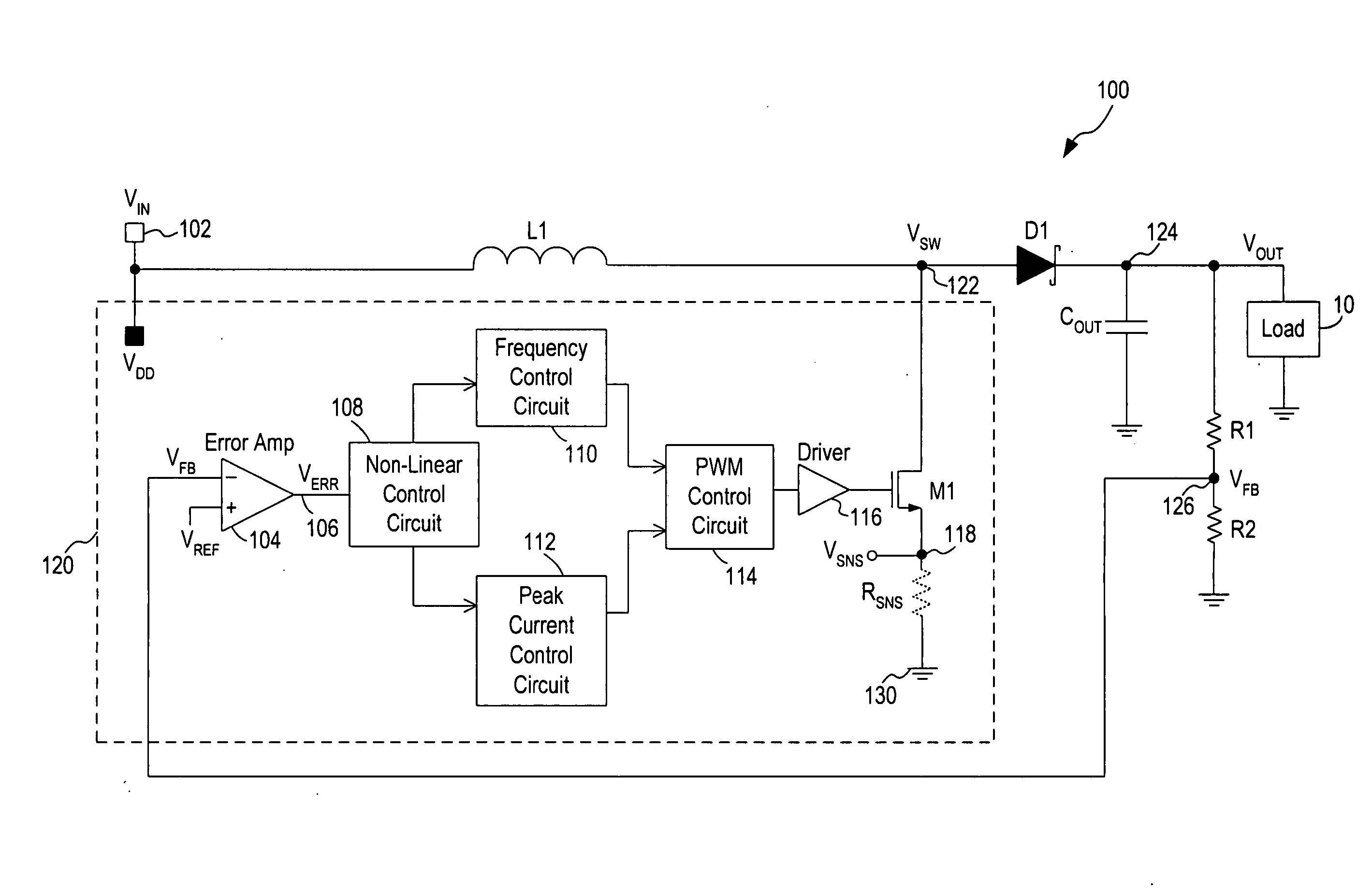
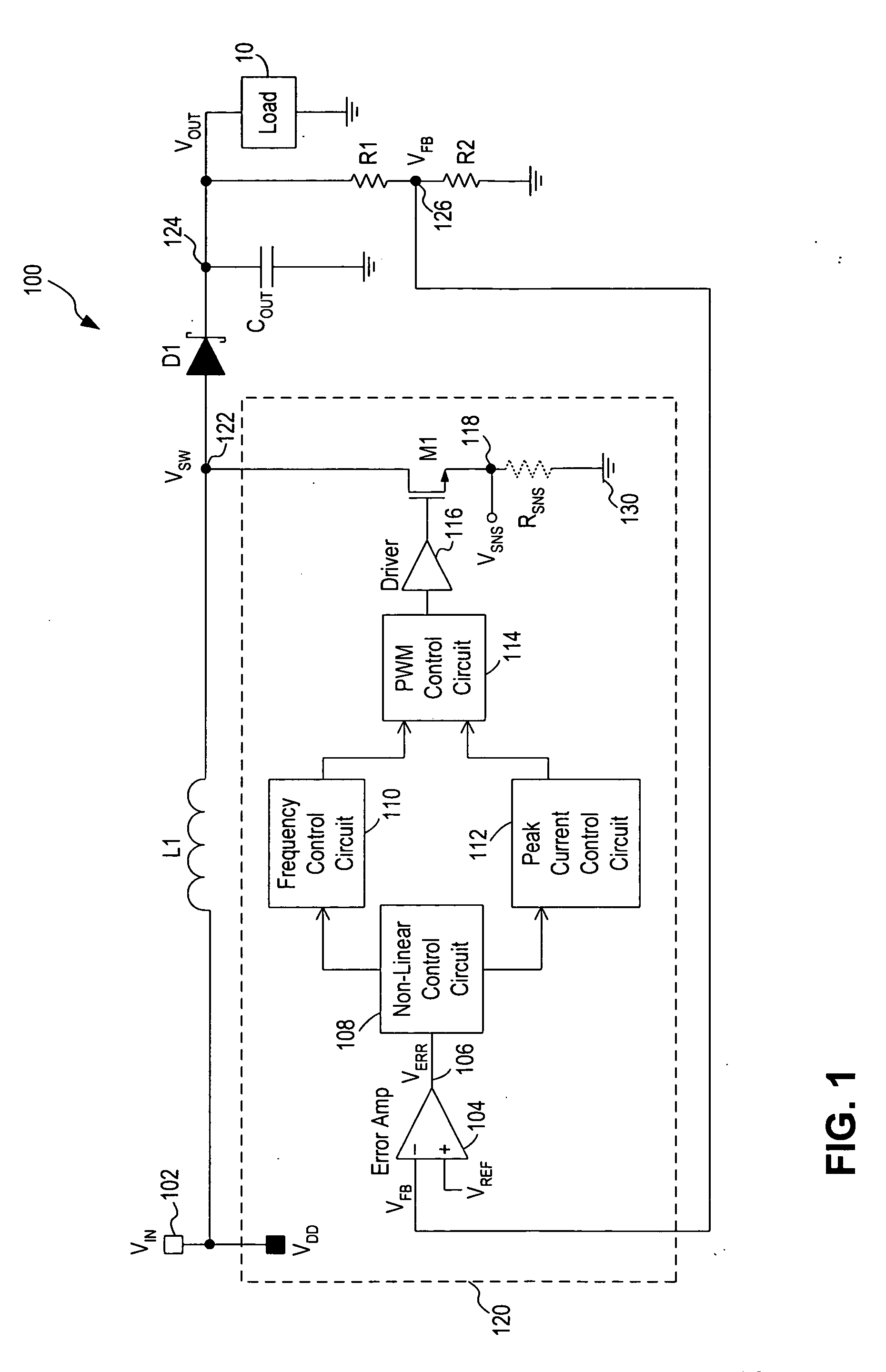
[0020] In accordance with the principles of the present invention, a switching regulator operates under a combination of variable off-time control (or frequency control) and variable peak current control to achieve high efficiency at a wide range of load conditions. In operation, the frequency control and the peak current control operate in conjunction over the entire range of load conditions with the frequency control dominates at light load (or low power) conditions and the variable peak current control dominates at heavy load (or high power) conditions. In effect, the two control schemes operate in parallel and the switching regulator transitions smoothly between frequency control and peak current control, with no defined operation boundary between the frequency control and peak current control. That is, the switching regulator operates under the continuous control of both the frequency control scheme and the peak current control scheme and does not toggle between the two control...


PUM


Abstract

A circuit and method for controlling a switching regulator utilize a combination of variable off-time control (or frequency control) and variable peak current control to achieve high efficiency at a wide range of load conditions. A non-linear control circuit receives an error voltage and generates a first control signal for controlling a frequency control circuit and a second control signal for controlling a peak current control circuit. The frequency control circuit and the peak current control circuit operate in conjunction over the entire range of load conditions with the frequency control dominates at light load (or low power) conditions and the variable peak current control dominates at moderate to heavy load (or high power) conditions. The switching regulator transitions smoothly between frequency control and peak current control with continous loop gain throughout the transition region.

Description

FIELD OF THE INVENTION [0001] The invention relates to switching regulators and, in particular, to a switching regulator implementing variable frequency and peak current control for maintaining high efficiency at all load conditions. DESCRIPTION OF THE RELATED ART [0002] DC voltage regulators or switching regulators operate to convert energy from one DC voltage level to another DC voltage level. A switching regulator, sometimes referred to as a switching mode power supply, provides power supply function through low loss components such as capacitors, inductors, and transformers, and power switches that are turned on and off to transfer energy from the input to the output in discrete packets. A feedback control circuit is used to regulate the energy transfer to maintain a constant output voltage within the desired load limits of the circuit. [0003] A switching regulator can be configured to step up the input voltage or step down the input voltage or both. Specifically, a buck switchi...

Claims


Application Information

Patent Timeline
Patent Type & Authority Applications(United States)
IPC IPC(8): G05F1/00
CPCH02M3/156H02M1/0032Y02B70/10
Inventor SAWTELL, CARL
Owner MICREL
Why Eureka
Try Eureka