

Laser irradiation apparatus
- Summary
- Abstract
- Description
- Claims
- Application Information
AI Technical Summary
Benefits of technology
Problems solved by technology
Method used
Image

Examples
Embodiment Construction
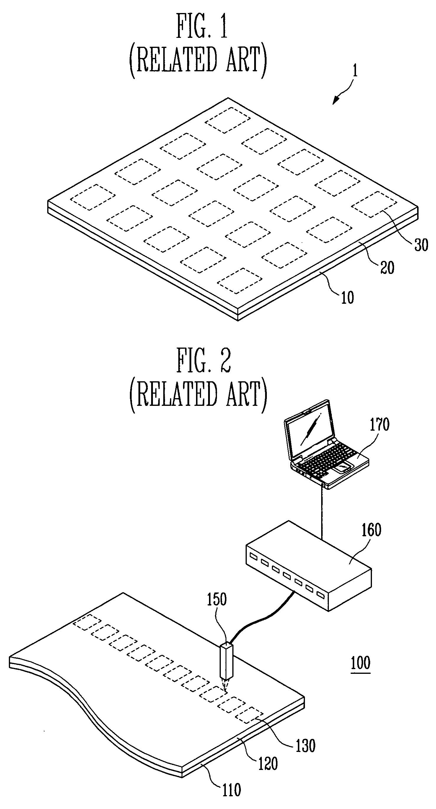
[0021]Turning now to the drawings, FIG. 1 is a perspective view showing a coalesced substrate obtained by coalescing a sealing substrate sheet with a base substrate sheet during a process of manufacturing a conventional organic light emitting display in a sheet unit. In FIG. 1, a sealant is used as a frit. As shown in FIG. 1, a coalesced substrate sheet 1 includes a base substrate sheet 10, a sealing substrate sheet 20, and frits 30. A plurality of organic light emitting diodes are formed on the base substrate sheet 10. The sealing substrate sheet 20 coalesces with the base substrate sheet 10. The frits 30 are disposed between the base substrate sheet 10 and the sealing substrate sheet 20, and seals the base substrate sheet 10 and the sealing substrate sheet 20 every organic light emitting diode.
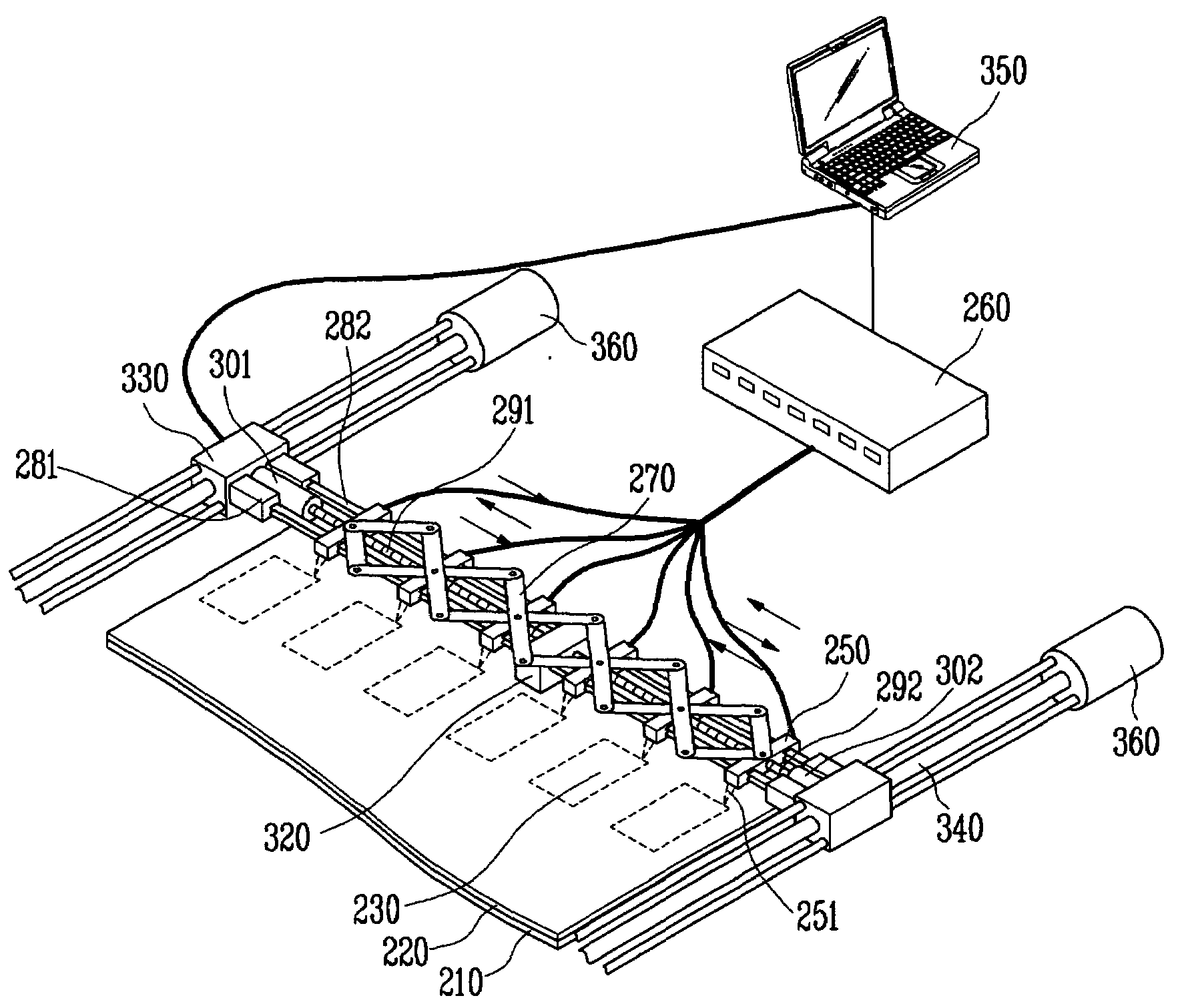
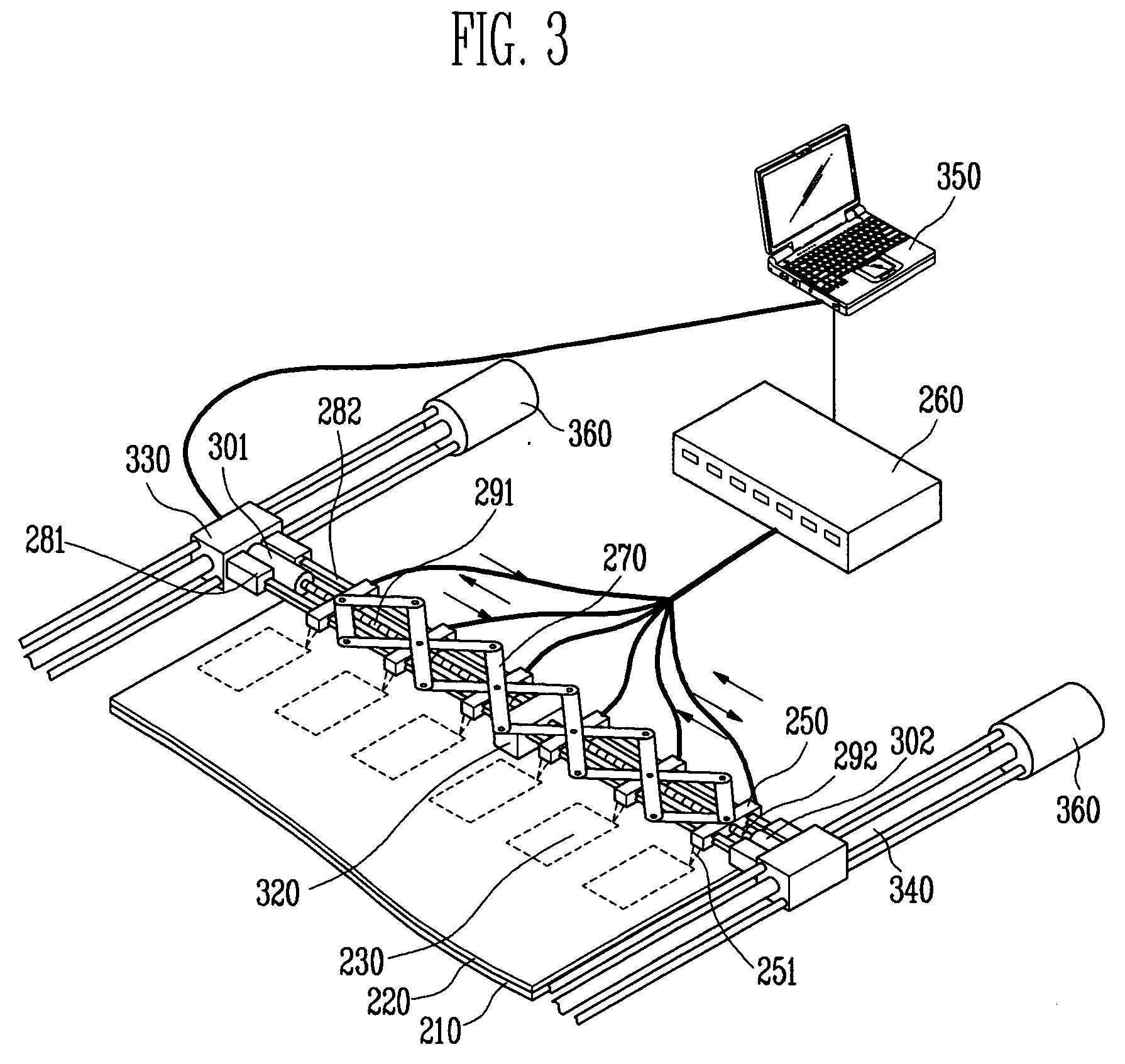
[0022]Here, a laser irradiation apparatus is used to coalesce the frit 30 coated and sintered at the sealing substrate sheet 20 with the base substrate sheet 10. FIG. 2 is a schematic view s...
PUM
| Property | Measurement | Unit |
|---|---|---|
| Angle | aaaaa | aaaaa |
| Wavelength | aaaaa | aaaaa |
| Wavelength | aaaaa | aaaaa |
Abstract
Description
Claims
Application Information