
Protection device

a protection device and positioning technology, applied in the direction of electric controllers, program control, instruments, etc., can solve the problems of speed and movement speed of machine parts, and achieve the effect of simplifying the aforementioned position and speed monitoring

Inactive Publication Date: 2007-09-13
ABB (SCHWEIZ) AG
View PDF9 Cites 22 Cited by
  • Summary
  • Abstract
  • Description
  • Claims
  • Application Information

AI Technical Summary

Benefits of technology

[0009] To simplify the aforementioned position and speed monitoring, a new arrangement is developed which considerably simplifies and provides additional safety possibilities.

Problems solved by technology

The speed a machine part moves is also an important issue for the safety design.

Method used


Image

  • Protection device
  • Protection device
  • Protection device

Examples


Embodiment Construction

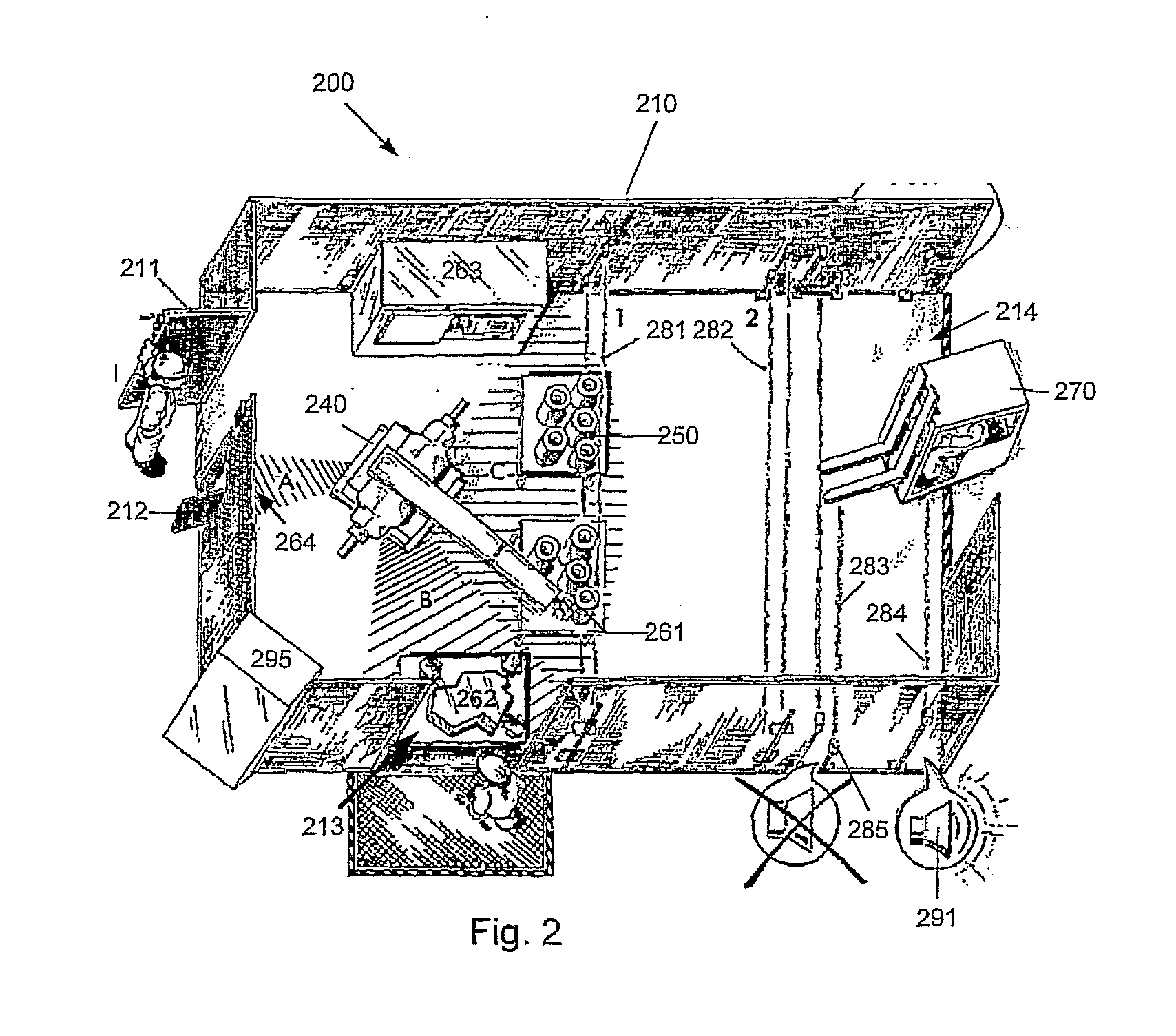
[0018] In the following the invention will be described in a non-limiting way with reference to monitoring of movements of an industrial robot. However, it is understood that the invention is not limited to the illustrated embodiments. The application areas extend to all applications in which moving devices, such as cranes, overhead cranes, conveyers, etc. occur.

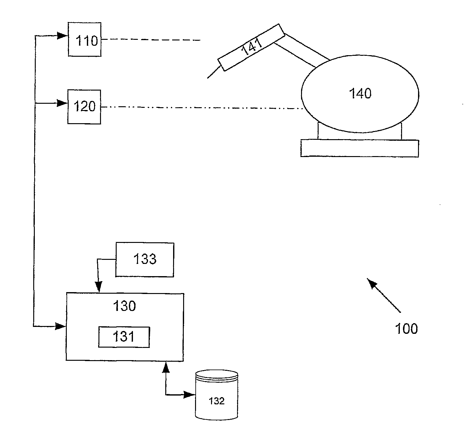
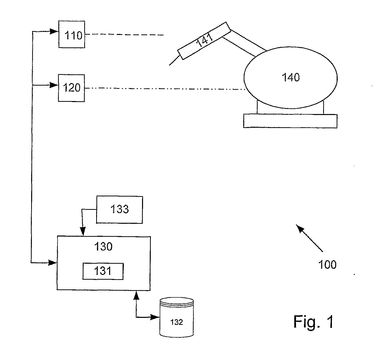
[0019] According to FIG. 1, the system 100 comprises at least two sensors 110 and 120 which provide position information to a safety monitoring unit 130. The fundamental condition is same as the today's system, i.e. double information about which position a machine part 141 of a machine, in this case a robot 140 is situated in, as well as assuming that no errors will occur in both sensors simultaneously.

[0020] In a mechanical design, the position of fixed notches which are designed so that two switches sense each section is guaranteed.

[0021] According to the invention, the detection comprises two sensors 110 and 120, whic...


PUM


Abstract

The present invention relates to a safety system for use in protection functions, which system prevents that an error in one control circuit do not result in a function failure by using supervising functions comprising at least two sensors connected to a monitoring unit which receives and processes information about a position of a machine from both sensors and compares the results with stored values and a number of input conditions for the monitoring unit, whereby said sensors comprise means for generating data with respect to a position of a machine movement and said monitoring unit comprises means, which with respect to the result of the comparison is arranged to stop a machine movement if conditions for a stop are fulfilled. The monitoring unit is arranged to compare values from said sensors and when detecting deviating value from either one of sensors detecting a functional error with the sensors.

Description

PRIORITY INFORMATION [0001] The present application is a continuation of PCT Application No. PCT / SE2005 / 001420, filed on Sep. 26, 2005 which claims priority to Swedish Application No. SE0402329-7, filed on Sep. 24, 2004. Both applications are incorporated herein by reference in their entireties.TECHNICAL FIELD [0002] The present invention relates to an arrangement for area restriction and monitoring position and speed. BACKGROUND OF THE INVENTION [0003] I many machines, it is important, form the safety point of view, that in a reliable way to know where a moving machine part is and also how fast it moves. For an industrial robot, for example, it is used to divide operation area into safe sectors. This means that if a person walks into the protected sector, then the robot is stopped only if it is in the same sector by using a safety device which detects if the person enters the sector. The sector in which the robot operates is usually detected by double switches which are affected by...

Claims


Application Information

Patent Timeline
IPC IPC(8): H02H7/08B25J9/16F16P3/14G07C
CPCB25J9/1674F16P3/14G05B2219/37372F16P3/144G05B2219/49137G05B2219/49142G05B2219/45083B25J13/089G05D3/128
Inventor SVENSSON, GORANLINGER, MATTS D.
Owner ABB (SCHWEIZ) AG
Learn More