Face Imaging Device

a face imaging and face technology, applied in the field of face imaging devices, can solve the problems of difficult to explain appropriately, difficult to compare objectively, and the direction of the face cannot be restricted upon

Inactive Publication Date: 2007-09-13
MORITEX CORP
View PDF10 Cites 23 Cited by
  • Summary
  • Abstract
  • Description
  • Claims
  • Application Information

AI Technical Summary

Benefits of technology

[0014] According to the present invention, a head and a jaw are supported in the casing, and the face is positioned to a focused focal point of the imaging camera.
[0015] In this case, since the head support member is put against a non-observation region on head top side such as a hair portion which is not necessary for image data when observing the skin, a necessary image is not concealed by the support member and the image of the necessary portion can be taken entirely
[0016] Further, the jaw rest restricts the position of the jaw in accordance with the imaging direction such that the front side of the face and the light or left cheek portion is faced to the imaging camera.
[0017] Accordingly, since the jaw is rested on the jaw rest and supported at a position in accordance with the direction of the face and the forehead is supported by the head support member, the image of the face can be taken at an identical distance and at an identical angle relative to the imaging camera.
[0018] In this case, by making the imaging region smaller than the face, since it does not suffer from the effect of the background brightness, the image can be taken at an identical brightness.
[0019] Further, since the light illuminated from the illumination light source is diffused through the light diffusion plate and illuminates the entire front side of the face at a uniform brightness, it does not cause shining.

Problems solved by technology

Accordingly, while it was possible for conducting informed consent of explaining the method of treatment, etc. before surgery only based on the image picked-up before the surgery and explaining the effect of treatment only based on the image picked-up after the surgery, since the brightness, etc. are different between two images picked-up before and after the surgery, they can not be compared objectively and it was difficult to explain them appropriately.
However, since the face can be imaged only from the front by the means, while skins in a T-shaped zone from a forehead to a nose and the front of cheeks can be taken, the direction of the face can not be restricted upon imaging the surface on the lateral side of the cheek.
Further, in a case of illuminating an illumination light, while a circular fluorescent lamp or an LED has been used as an illumination light source, when the illumination light is illuminated directly to the face, this partially results in shining and the state of the skin can not be recognized accurately based on the picked-up images
While shining at the face skin was not caused, since the imaging camera and the illumination light source are situated on the identical side relative to the light diffusion plate, this resulted in an additional problem that a portion of a light illuminated from the illumination light source directly enters the imaging camera or a reflection light reflected at the back of the light diffusion plate enters the imaging camera thereby causing a weak halation to a portion of a screen making the thus image not clear.

Method used


Image

  • Face Imaging Device
  • Face Imaging Device
  • Face Imaging Device

Examples


embodiment 1

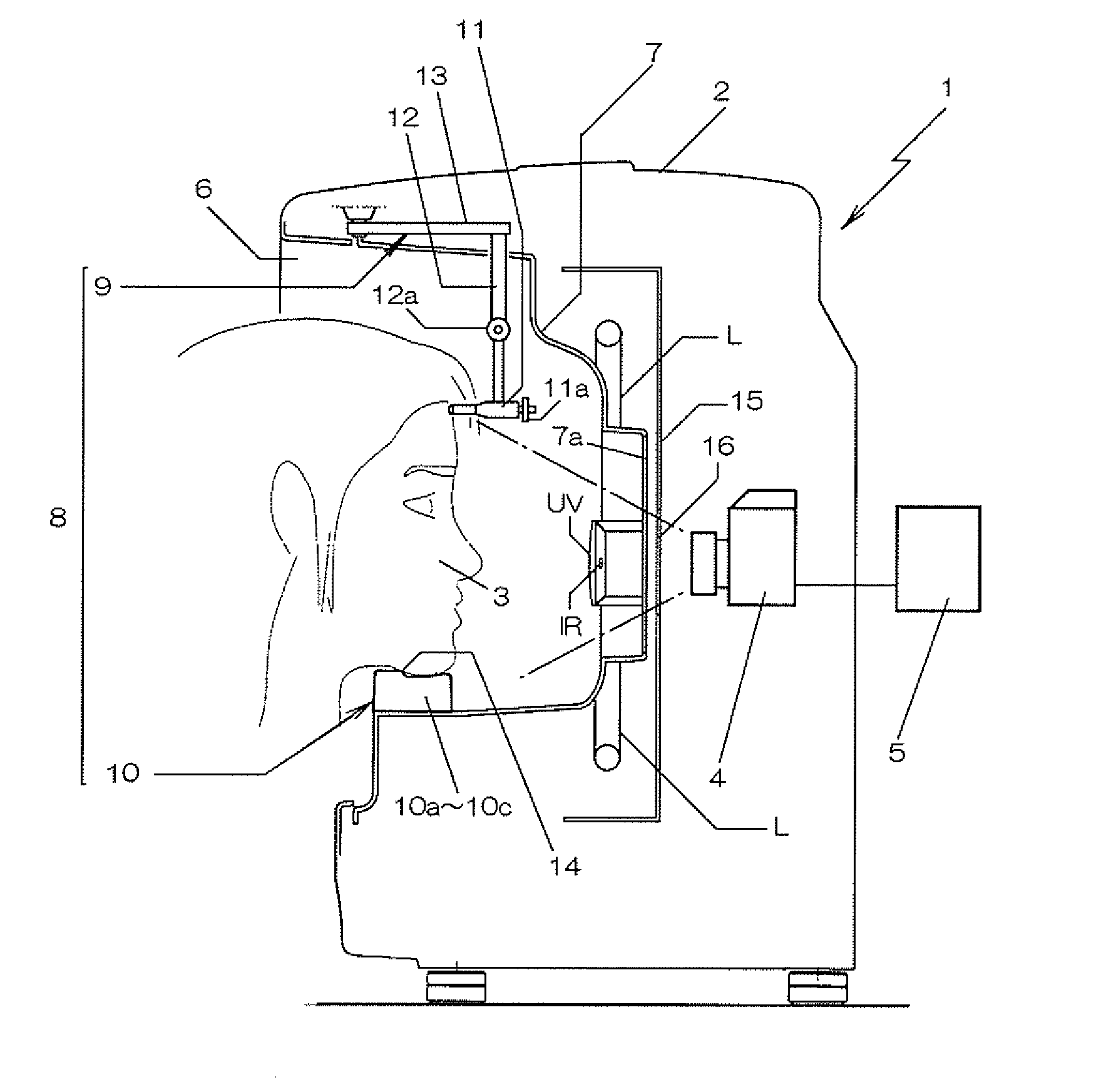
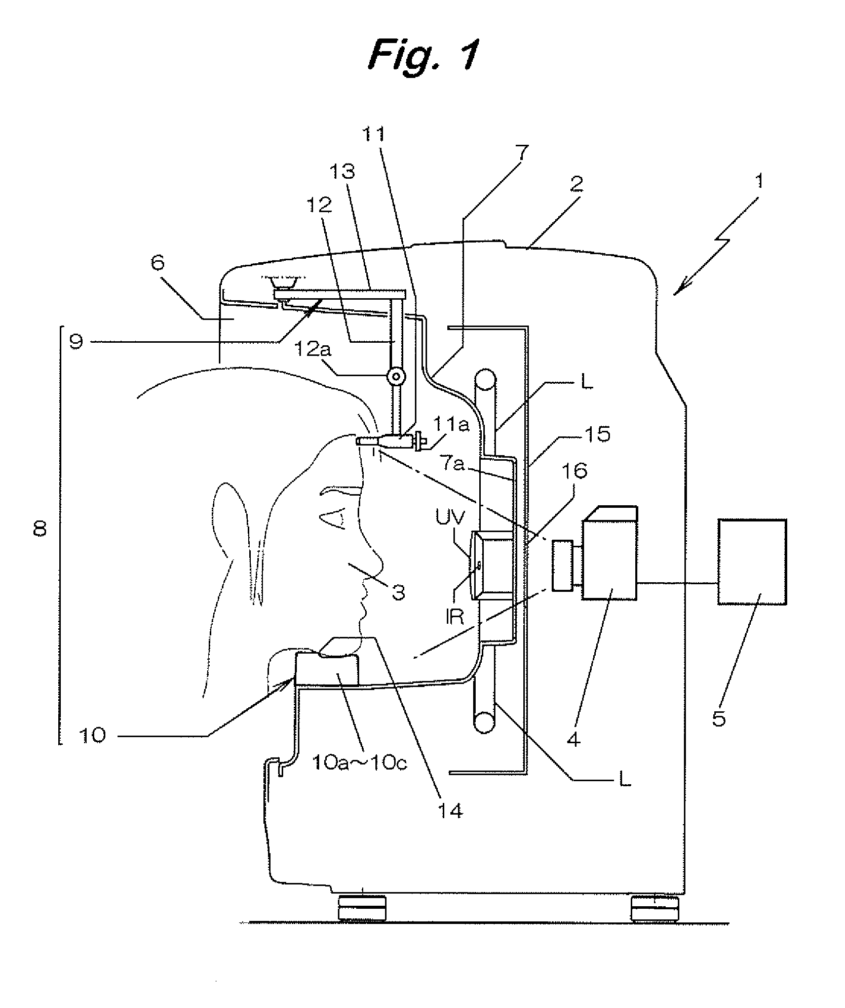
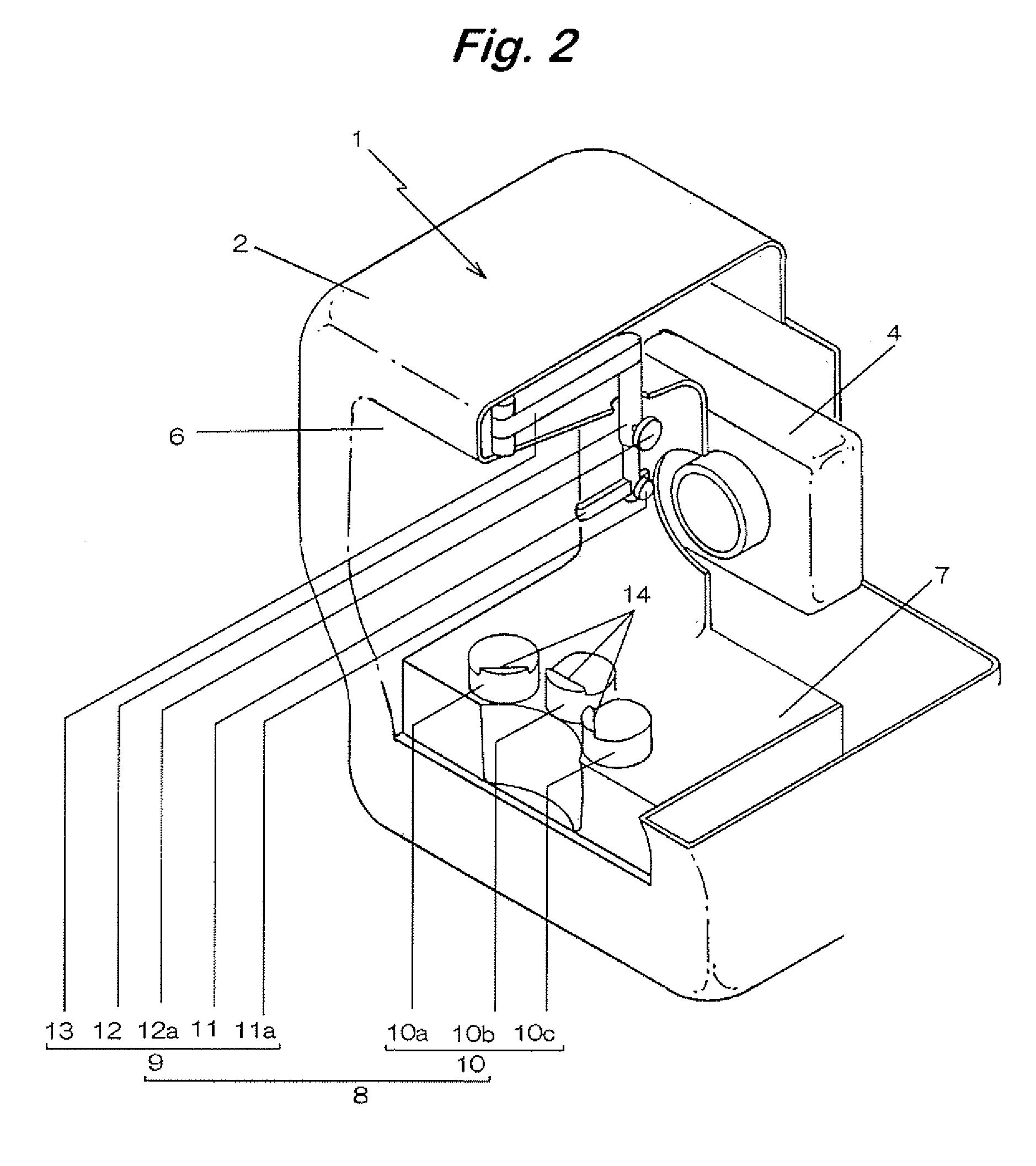
[0028] A face imaging device 1 shown in FIG. 1 to FIG. 3 has an imaging camera 4 for imaging a face 3 provided in a casing 2 in which an image signal outputted from the imaging camera 4 can be taken into a computer 5 and projected.

[0029] An opening 6 for inserting the face 3 is formed at the front of the casing 2, an illumination light source L for illuminating a visible light to the face 3 is located to the inside thereof, an opaque light diffusion plate 7 is situated between the opening 6 and the illumination light source L for diffusing the light illuminated from the illumination light source L and illuminating the front side of the face 3, and an imaging camera 4 for imaging the face through a permeation hole 7a formed in the light diffusion plate 7 is disposed at the back thereof.

[0030] In this embodiment, a circular or straight tubular white light emission tube W is used as the illumination light source L, which is disposed so as to surround the optical axis of the imaging c...

example 2

[0061]FIG. 4 shows another embodiment of the invention. In this embodiment, a head support member 21 is disposed such that it can not be moved and it comprises a vertical position adjusting shaft 24 in which a support shaft 23 having two protrusions 22R, 22L for supporting the head top non-observation region of the face 3 at two right and left points formed at the top end is attached to the lower end. The head support member 21 is fixed instead of the head support member 9 to the ceiling portion of a casing of the face imaging device 1 shown in FIG. 1.

[0062] The support shaft 23 is provided with a forward-to-backward position adjusting knob 23a for adjusting the forward-to-backward position thereof, and a vertical position adjusting shaft 24 is provided with a vertical position adjusting knob 24a for adjusting the vertical position of the support shaft 23.

[0063] The head support member 21 is fixed instead of the head support member 9 to the ceiling portion of the face imaging devi...


PUM


Abstract

A face imaging device having an illumination light source for illuminating a visible light to a face is disposed in a casing having an opening formed at the front thereof for inserting the face as an object to be imaged. A light diffusion plate is disposed between the opening and the illumination light source for diffusing a light illuminated from the illumination light source to the front side of the face, and an imaging camera for imaging the face through a permeation hole formed in the light diffusion plate is located at the back thereof. A face holding mechanism holds the face as an object at a focused focal point of the imaging camera by a head support member capable of adjusting the forward-to-backward and vertical positions for restricting the position of a head by abutment against a head top non-observation region of the face inserted in the casing, and a jaw rest restricts the position of the jaw in accordance with the imaging direction such that the front and the right or left cheeks of the face are faced to the imaging camera. A light shielding body is located between the illumination light source and the imaging camera for shielding a light incident to the imaging camera without transmitting the permeation hole, among the lights illuminated from the illumination light source.

Description

TECHNICAL FIELD [0001] The present invention concerns a face imaging device capable of imaging a face from plural directions under an identical imaging condition. BACKGROUND ART [0002] Laser treatment of irradiating a laser light to a skin surface and subcutaneous portions to be treated has been conducted, for example, in dermatology, plastic surgery, orthopedic surgery, etc. [0003] Particularly, in a case where a portion to be treated is present on a face such as in the therapy for pimples, since patient can not directly observe the portion to be treated, a doctor puts an image taken by a digital camera into a computer and projects the same on a monitor for conducting informed consent before surgery operation or confirmation for the effect of treatment and explanation to the patient after surgery. [0004] However, in a case of imaging the portion to be treated, since an image is taken at an optional distance, the size of the portion to be treated differs subtly, as well as the brigh...

Claims


Application Information

Patent Timeline
Patent Type & Authority Applications(United States)
IPC IPC(8): G03B15/14A61B3/15A61B5/00A61B5/103A61B5/107A61B19/00
CPCA61B3/152A61B5/0077A61B5/6814A61B5/441A61B19/52A61B5/103A61B90/36
Inventor ASAI, YOSHIYUKISUEYOSHI, NAOJI
Owner MORITEX CORP
Why Eureka
Try Eureka