Fixing and release systems

a technology of fixing and release system, applied in the direction of electrical/magnetic/electromagnetic heating, couplings, furniture parts, etc., can solve the problems of affecting the repair effect of the element, the fixing method is visible externally, and the common method of fixing is rarely reversible without damage to the element being fixed, etc., to achieve the effect of easy removal for renovation and quick installation

Inactive Publication Date: 2007-09-13
TELEZYGOLOGY
View PDF99 Cites 18 Cited by
  • Summary
  • Abstract
  • Description
  • Claims
  • Application Information

AI Technical Summary

Benefits of technology

[0011] Preferably, the fixing and / or the release can be effected without marking or damaging the first and second elements.
[0077] It will be readily appreciated by those skilled in the art that “on board technology” enables the manufacturer of the elements to build in added value to the elements, and increase the profit of the manufacturer, since a higher price may be charged for the elements with “on board technology”, because subsequent treatment may be reduced.

Problems solved by technology

Primitive versions, such as nails and screws, are labour intensive and have the drawback that the fixing means are visible externally.
This is labour intensive and generally results in post-finishing.
Further, common methods of fixing are rarely reversible without damage to the elements being fixed.

Method used


Image

  • Fixing and release systems
  • Fixing and release systems
  • Fixing and release systems

Examples


Embodiment Construction

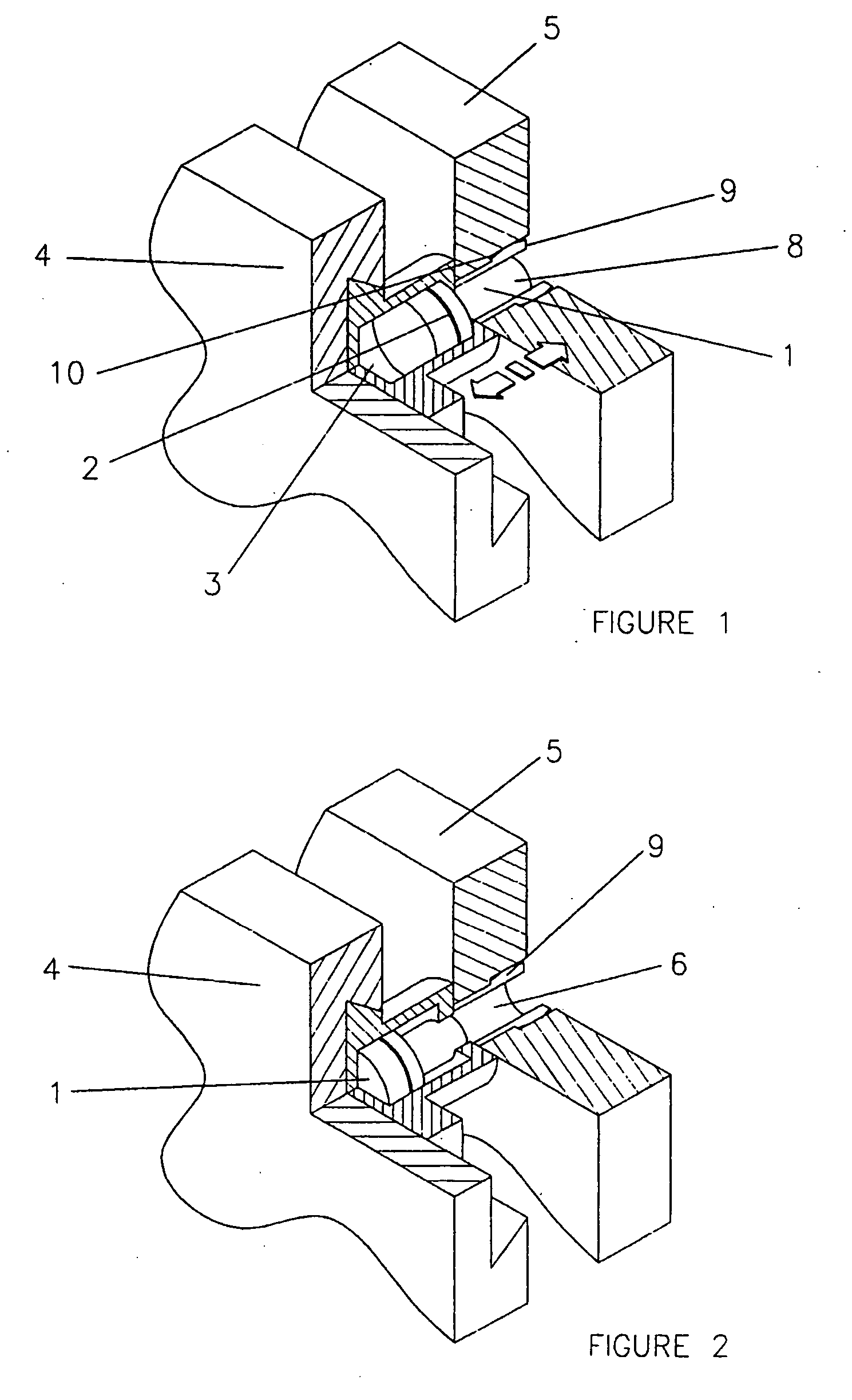
[0143] Referring first to FIG. 1, locking pin 1 is injection moulded from a suitable plastic material and includes a metal strip 2. Locking pin 1 lies in recess 3 between first element 4 and second element 5. Recess 3 has a narrow end 6 which lies within element 5.

[0144] When a magnetic force is applied to locking pin 1, it is caused to move within recess 3 as shown in FIG. 2, so that leg 8 of locking pin 1 is pushed into narrow recess 6, in turn expanding wall 9 so that it locks into the recess 10 provided in element 5.

[0145] Locking pin 1 may be reversed, so that elements 4 and 5 may be released, by the use of magnetic force. Magnetic attraction may be applied for fixing elements 4 and 5 and magnetic repulsion for releasing them, or vice versa. Alternately, the same magnetic force may be applied on opposite sides—for example, on the side near element 4 for fixing and on the side near element 5 for releasing.

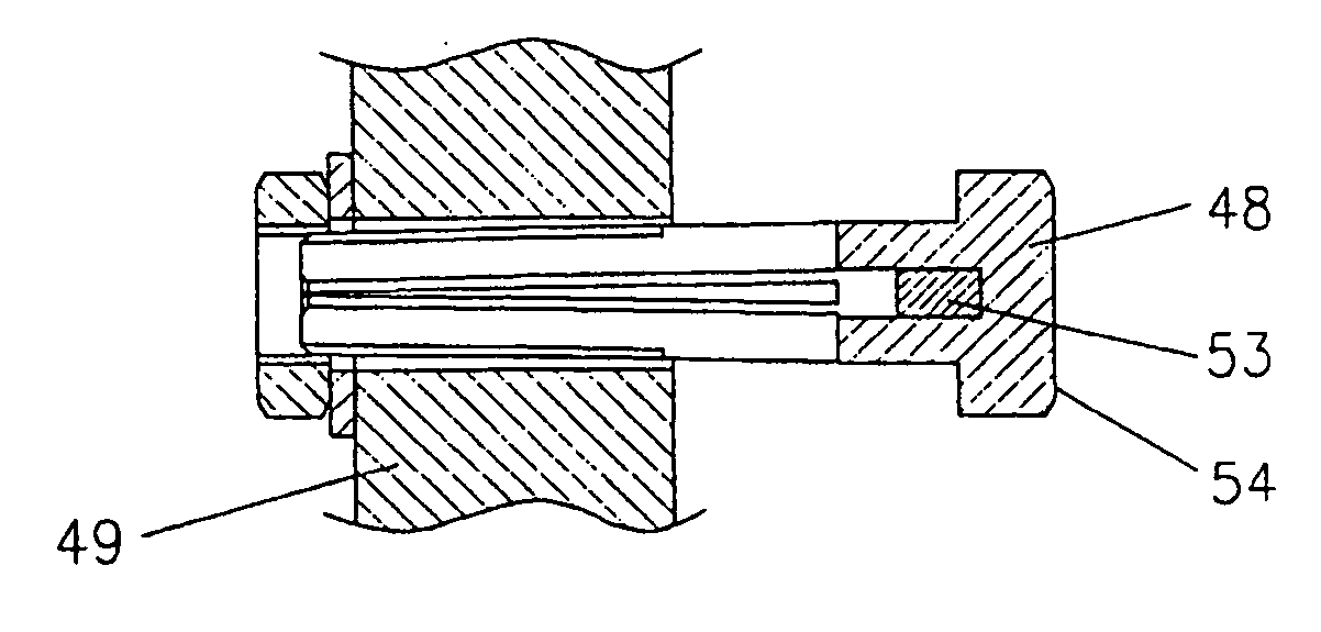
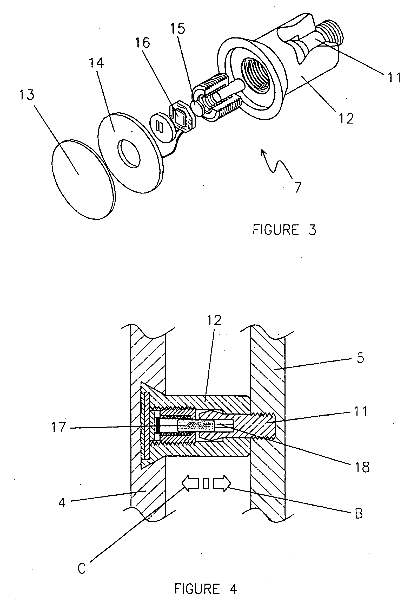
[0146] Turning now to FIG. 3, the connecting means 7 illustrated includ...


PUM


Abstract

A connecting means adapted to releasably fix or release a first element (4) and a second element (5) includes a locking pin (1) which is moveable by remote activation means between a locked position, in which leg (8) expands wall (9) into recess (10), and an unlocked position. The remote activation means may be magnetic, electromagnetic or any other suitable means. There is no permanent material connection between the pin (1) and the remote activation means. A method of fixing or releasing first and second elements by remote activation means is also disclosed. The invention further provides an embodiment where the first element is a first panel and the second element is a second panel. The first panel has means (166 or 169) which co-ordinate with means (165 or 170) on the second panel. A method of manufacturing the first element includes the steps of depositing discrete amounts of setable material on a surface of the first element and inverting the element to permit the material to set under the influence of gravity. A method of reducing the spacing between first and second elements by remote activation means is also disclosed.

Description

CROSS-REFERENCE TO RELATED APPLICATIONS [0001] This application is a continuation of U.S. patent application Ser. No. 09 / 646,741, filed Sep. 18, 2000, which is a national phase entry of International Patent Application No. PCT / AU99 / 00185, filed Mar. 18, 1999, which claims priority to Australian Patent Application Number PP2477, filed Mar. 18, 1998. These prior applications are all hereby incorporated by reference herein in their entireties.TECHNICAL FIELD [0002] This invention lies in the field of fixing and / or release systems for a myriad of products and applications. This invention also relates to connectors for use in fixing and release systems. BACKGROUND ART [0003] The need to fix one element to another, such as a panel to a stud, has given rise to a large technology relating to fasteners. Primitive versions, such as nails and screws, are labour intensive and have the drawback that the fixing means are visible externally. It is desirable to fix one element to another so that th...

Claims


Application Information

Patent Timeline
Patent Type & Authority Applications(United States)
IPC IPC(8): F16B21/12E04B2/74F16B1/00E04B2/82F16B5/06F16B11/00F16B13/06F16B17/00F16L25/00
CPCE04B2/7457E04B2002/7461E04B2002/7468F16B5/065F16B5/0657Y10T403/598F16L25/0018Y10S403/01Y10T403/4924Y10T403/593F16B5/0664
Inventor RUDDUCK, DICKORY
Owner TELEZYGOLOGY
Why Eureka
Try Eureka