Radially-compact assembly between a turbine shaft and a stub axle of a turbomachine compressor shaft

a technology of turbomachine and turbine shaft, which is applied in the direction of machines/engines, mechanical equipment, liquid fuel engines, etc., can solve the problems of disproportionate radial size and assembly type disadvantages, and achieve the effect of reducing such drawbacks

Active Publication Date: 2007-09-13
SN DETUDE & DE CONSTR DE MOTEURS DAVIATION S N E C M A
View PDF3 Cites 29 Cited by
  • Summary
  • Abstract
  • Description
  • Claims
  • Application Information

AI Technical Summary

Benefits of technology

[0004] A main aim of the present invention is thus to mitigate such drawbacks by providing an assembly that is radially compact.

Problems solved by technology

That type of assembly presents the drawback of possessing a radial size that is relatively large.
Such radial size is particularly harmful when dimensioning low-pressure turbine shafts for a contra-fan type turbomachine (i.e. when there are two contrarotating fans mounted at the front).

Method used


Image

  • Radially-compact assembly between a turbine shaft and a stub axle of a turbomachine compressor shaft
  • Radially-compact assembly between a turbine shaft and a stub axle of a turbomachine compressor shaft
  • Radially-compact assembly between a turbine shaft and a stub axle of a turbomachine compressor shaft

Examples


Embodiment Construction

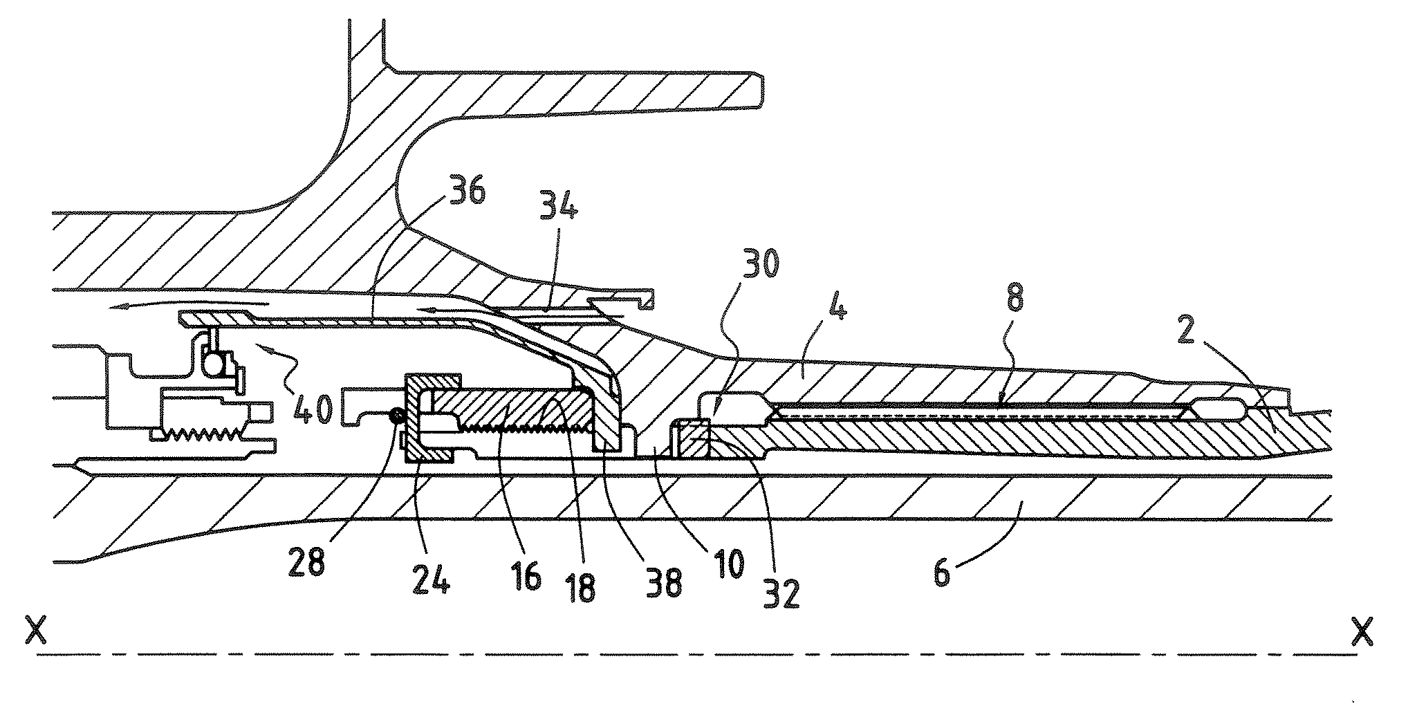
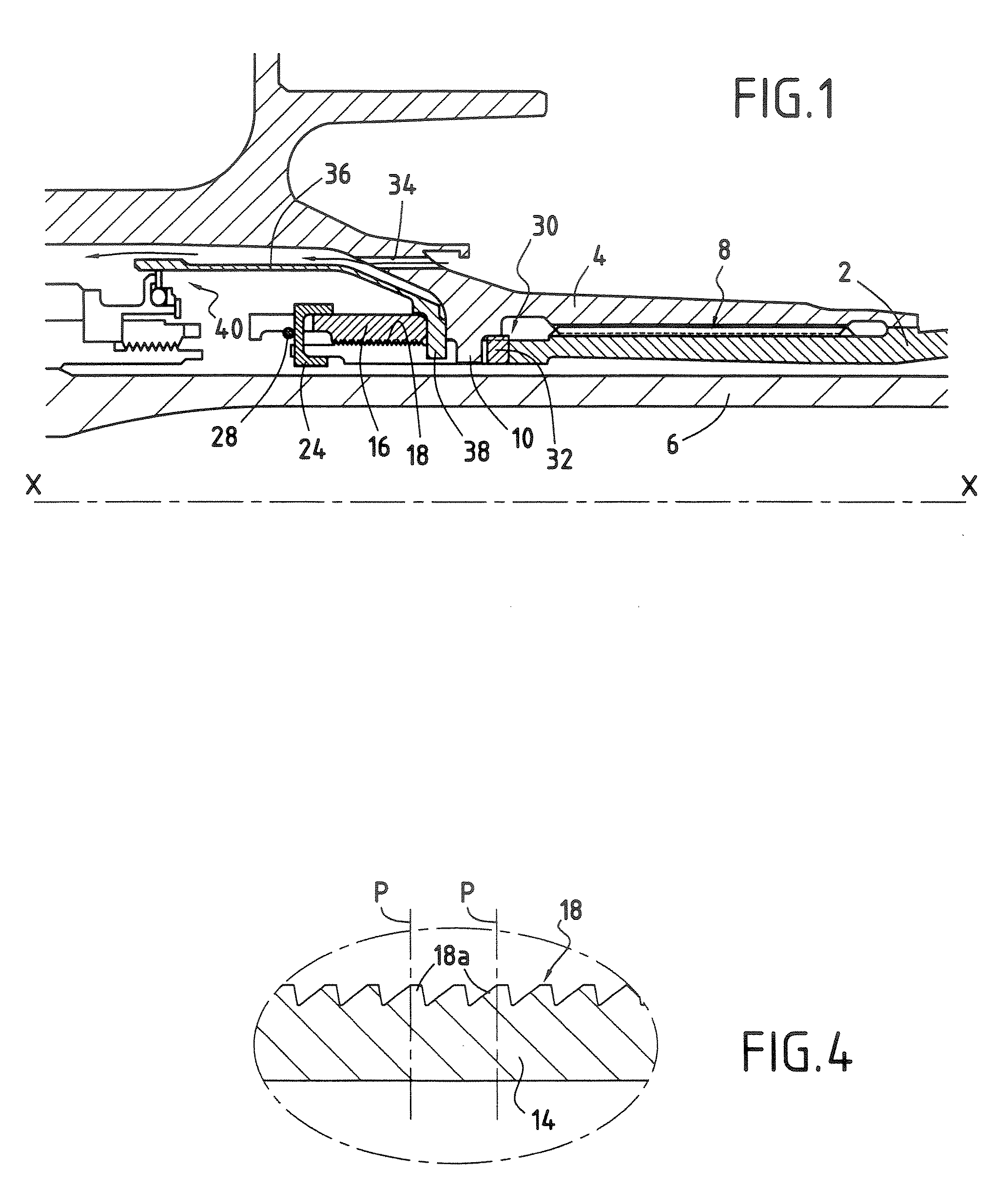
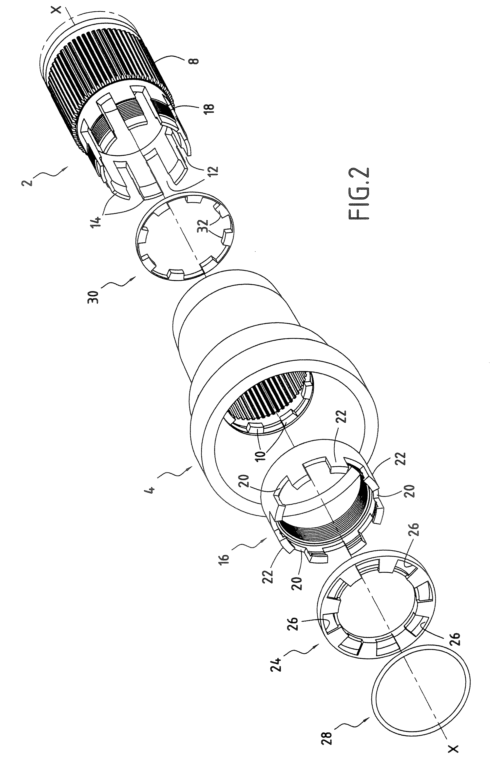
[0017] With reference to FIG. 1, the assembly of the invention comprises a substantially cylindrical turbine shaft 2 centered on a longitudinal axis X-X of a turbomachine. The assembly also comprises a compressor shaft stub axle 4 which is also substantially cylindrical.

[0018] For an application to a turbomachine of the contra-fan type, the turbine shaft 2 may for example be the outer low-pressure turbine shaft (as opposed to the inner low-pressure turbine shaft given reference 6 in FIG. 1), and the stub axle 4 may be that of the low-pressure compressor shaft.

[0019] Naturally, the invention is not limited to an application to a turbomachine of the contra-fan type, and it extends to any turbomachine presenting an assembly of this type.

[0020] The turbine shaft 2 is disposed coaxially inside the compressor shaft stub axle 4. In well-known manner, torque is transmitted between the turbine shaft 2 and the stub axle 4 by means of fluting 8.

[0021] According to the invention, the compre...


PUM


Abstract

The invention relates to an assembly between a turbine shaft and a stub axle of a turbomachine compressor shaft, the assembly comprising a substantially cylindrical compressor shaft stub axle, a substantially cylindrical turbine shaft disposed coaxially inside the compressor shaft stub axle, means for transmitting torque between the turbine shaft and the compressor shaft stub axle, and clamping means for clamping a downstream end of the turbine shaft to the compressor shaft stub axle. The compressor shaft stub axle has a plurality of teeth extending radially from its inside surface, and the turbine shaft is provided at its downstream end with a plurality of axial slots, the teeth of the stub axle co-operating with the slots of the turbine shaft.

Description

BACKGROUND OF THE INVENTION [0001] The present invention relates to the general field of turbomachines in which the shaft of the low-pressure spool comprises a turbine shaft assembled to a stub axle of a compressor shaft. The invention relates more precisely to an assembly of this type that is radially compact. [0002] In a turbomachine, the gas coming from combustion of an air / fuel mixture drives the low-pressure turbine in rotation. This turbine has a low-pressure turbine shaft that is coupled to a low-pressure compressor shaft in order to rotate the low-pressure compressor of the turbomachine. For this purpose, the high-pressure turbine shaft is housed inside a stub axle of the low-pressure compressor shaft which is coupled thereto by fluting. A nut is tightened onto the downstream end of the low-pressure turbine shaft and serves to hold this coupling together, axially. More precisely, the stub axle of the low-pressure compressor shaft presents an internal annular collar that come...

Claims


Application Information

Patent Timeline
Patent Type & Authority Applications(United States)
IPC IPC(8): F04D29/00
CPCF01D5/026F05D2250/182F05B2260/301F02C7/36
Inventor GUIHARD, FREDERICCHARIER, GILLES ALAIN
Owner SN DETUDE & DE CONSTR DE MOTEURS DAVIATION S N E C M A
Why Eureka
Try Eureka