
Surgical retractor frame system

a retractor frame and surgical technology, applied in the field of clamps, can solve the problems of not providing tactile feedback to the operator, relatively large space envelope for operation, and device limitations, and achieve the effects of positive clamping and tactile feedback, easy modification, and greater clamping for

Inactive Publication Date: 2007-09-13
BOSS INSTR
View PDF7 Cites 108 Cited by
  • Summary
  • Abstract
  • Description
  • Claims
  • Application Information

AI Technical Summary

Benefits of technology

[0009] According to another embodiment, the coupling clamp, frameset clamp, and / or retractor clamp can generate greater clamping forces than today's surgical retraction assemblies without excessive operator effort. The over-center toggle locking mechanism of the coupling clamp, frameset clamp, and / or retractor clamp provides positive clamping and tactile feedback to the user. The design of the toggle locking members can be easily modified to obtain customized output motions and force profiles, unlike threaded screw or cam locking devices which are fixed by their initial design.
[0010] According to another embodiment, the toggle mechanism of the coupling clamp, frameset clamp, and / or retractor clamp can achieve desired motion outputs with relatively short input lever motions. This reduces the space envelope required to operate the coupling clamp, frameset clamp, and / or retractor clamp, allowing them to be used in tighter spaces and creating less interference with the surgical sterile field. Additionally, the toggle mechanism can be locked and unlocked by an operator with one hand.

Problems solved by technology

While such systems according to the prior art individually provide a number of advantageous features, they nevertheless have certain limitations.
Furthermore, such devices do not provide tactile feedback to the operator to indicate when positive clamping has been achieved.
And, most require a relatively large space envelope for operation.

Method used


Image

  • Surgical retractor frame system
  • Surgical retractor frame system
  • Surgical retractor frame system

Examples


Embodiment Construction

[0044] While this invention is susceptible of embodiments in many different forms, there is shown in the drawings and will herein be described in detail preferred embodiments of the invention with the understanding that the present disclosure is to be considered as an exemplification of the principles of the invention and is not intended to limit the broad aspect of the invention to the embodiments illustrated.

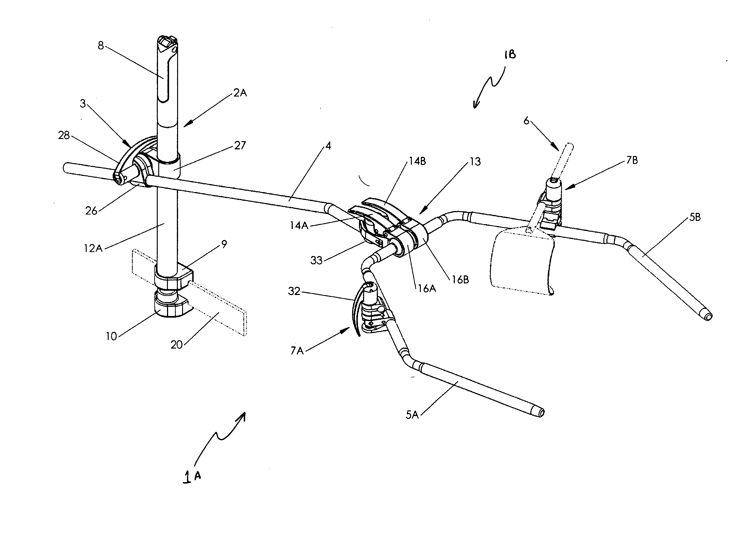
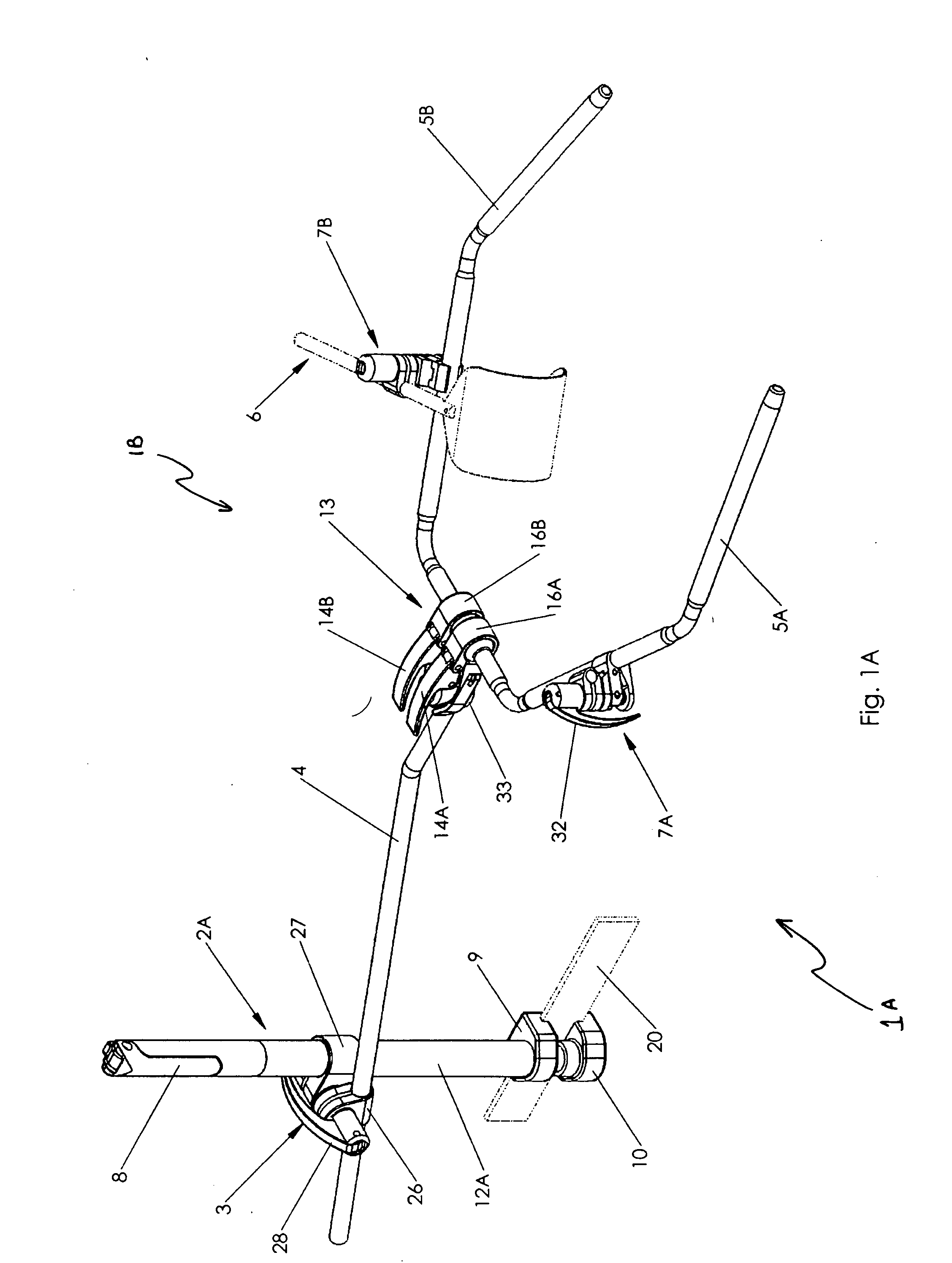
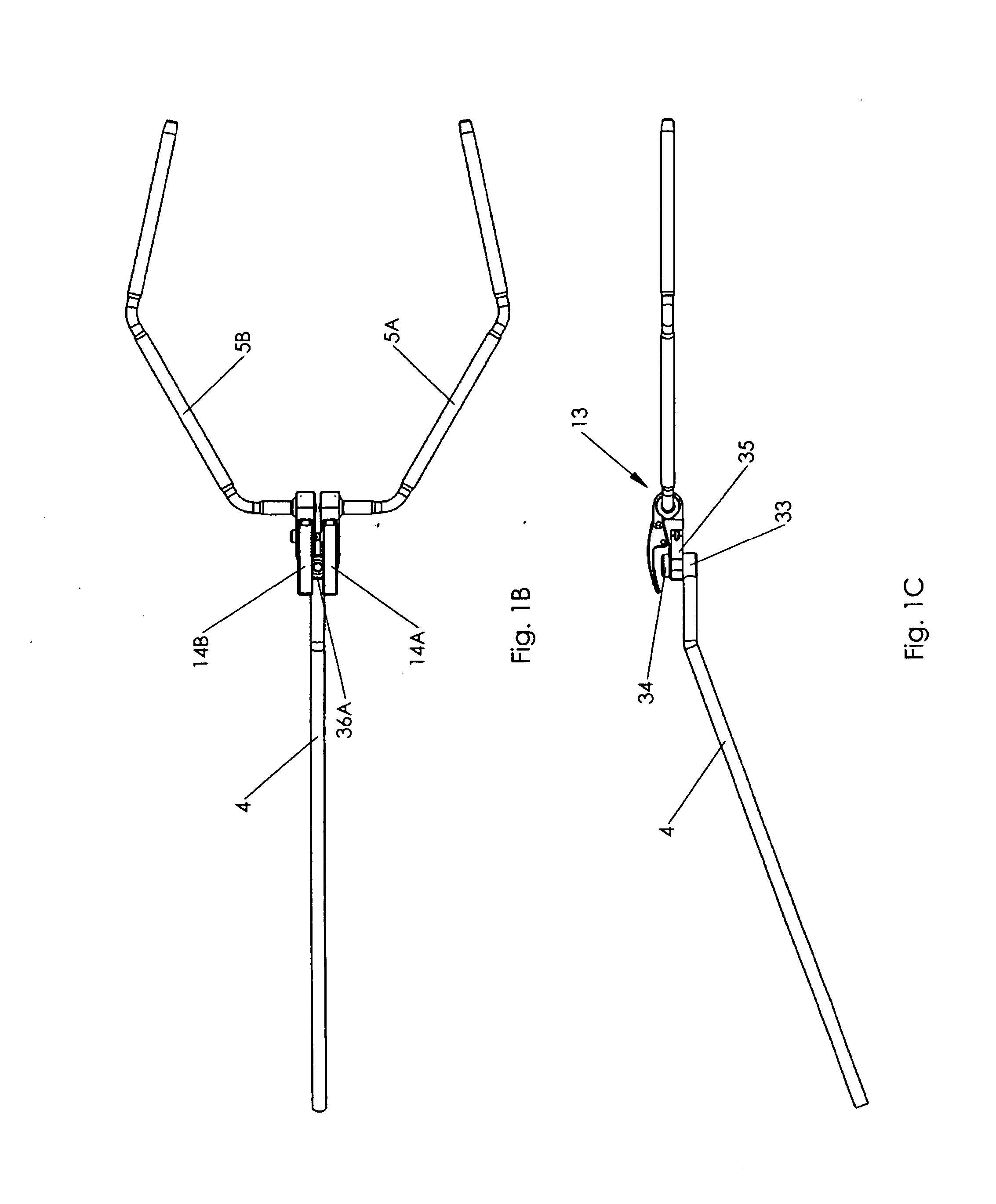
[0045] Referring now to the Figures, and specifically to FIG. 1A, there is shown a surgical retractor frame system 1A comprised of frame 1B, and table post 2A, with at least one toggle clamp connecting the various parts of the frame 1B or connecting the frame 1B to the table post 2A. Other embodiments or the present invention presented herein are a variety of toggle clamps, such as coupling clamp 3, table post 2A with an integral table post rail clamp 2B, retractor clamp 7A and frameset clamp 13. Frame 1B is comprised of a support arm 5, frameset clamp 13, extension beam 4, a...


PUM


Abstract

The present invention generally provides a surgical clamp for use with a surgical retractor support frame. The surgical clamp has a handle that rotates about a first pivot point from a first position to a second position, and a second pivot point eccentric to the first pivot point. The surgical clamp also has an intermediate link with a first portion that rotates about the second pivot point and a second portion that is rotatably connected to a third pivot point on an output link. The intermediate link is manipulated by rotation of the handle, and the intermediate link further manipulates the output link from a first position to a second position. The output link is operably connected to at least one of the first and second clamps to apply a clamping force on a surgical instrument to lock the surgical instrument in place.

Description

CROSS-REFERENCE TO RELATED APPLICATIONS [0001] This application is a continuation-in-part of U.S. Provisional Patent Application Ser. No. 60 / 777,771, filed on Mar. 1, 2006, which is expressly incorporated herein by reference and made a part hereof.FEDERALLY SPONSORED RESEARCH OR DEVELOPMENT [0002] Not Applicable. TECHNICAL FIELD [0003] The present invention relates generally to clamps, and more specifically to toggle clamps and their use in surgical retractor frame systems. BACKGROUND OF THE INVENTION [0004] Surgical retractor assemblies are used to hold incisions open and keep anatomical structures out of the way so the surgeon can have unobstructed access to a surgical site. Many of today's surgical retractor assemblies use either threaded screws or cam devices to lock various members of retractor assemblies in position. While such systems according to the prior art individually provide a number of advantageous features, they nevertheless have certain limitations. For example, thr...

Claims


Application Information

Patent Timeline
IPC IPC(8): A61B1/32
CPCA61B17/02A61B17/0293A61B2019/268A61B19/26A61B17/0206A61B90/50A61B2090/571
Inventor WOOSTER, NICHOLAS H.
Owner BOSS INSTR
Learn More