Integrated Thermal System

a thermal energy system and integrated technology, applied in the field of integrated thermal energy systems, can solve the problems of insufficient simple geothermal system to meet the needs of the building, inconvenient installation and maintenance, and inconvenient maintenance and maintenance,

Inactive Publication Date: 2007-09-20
LEWKOWITZ MICHAEL ALEXANDER BALDWIN +2
View PDF7 Cites 29 Cited by
  • Summary
  • Abstract
  • Description
  • Claims
  • Application Information

AI Technical Summary

Problems solved by technology

However, a simple geothermal system is often not sufficient to meet the needs of the building it services.
However, such conventional integrated systems have some drawbacks.
One problem is that such integrated systems often require expensive and extensive additional equipment and control components, such as additional pumps, valves and the like.

Method used


Image

  • Integrated Thermal System
  • Integrated Thermal System
  • Integrated Thermal System

Examples


Embodiment Construction

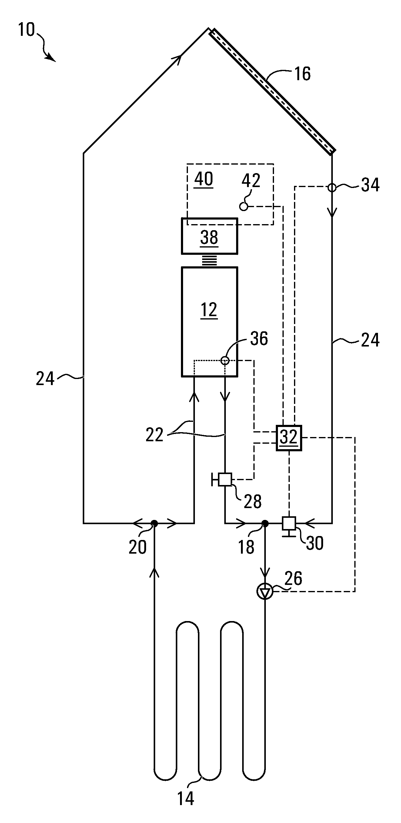
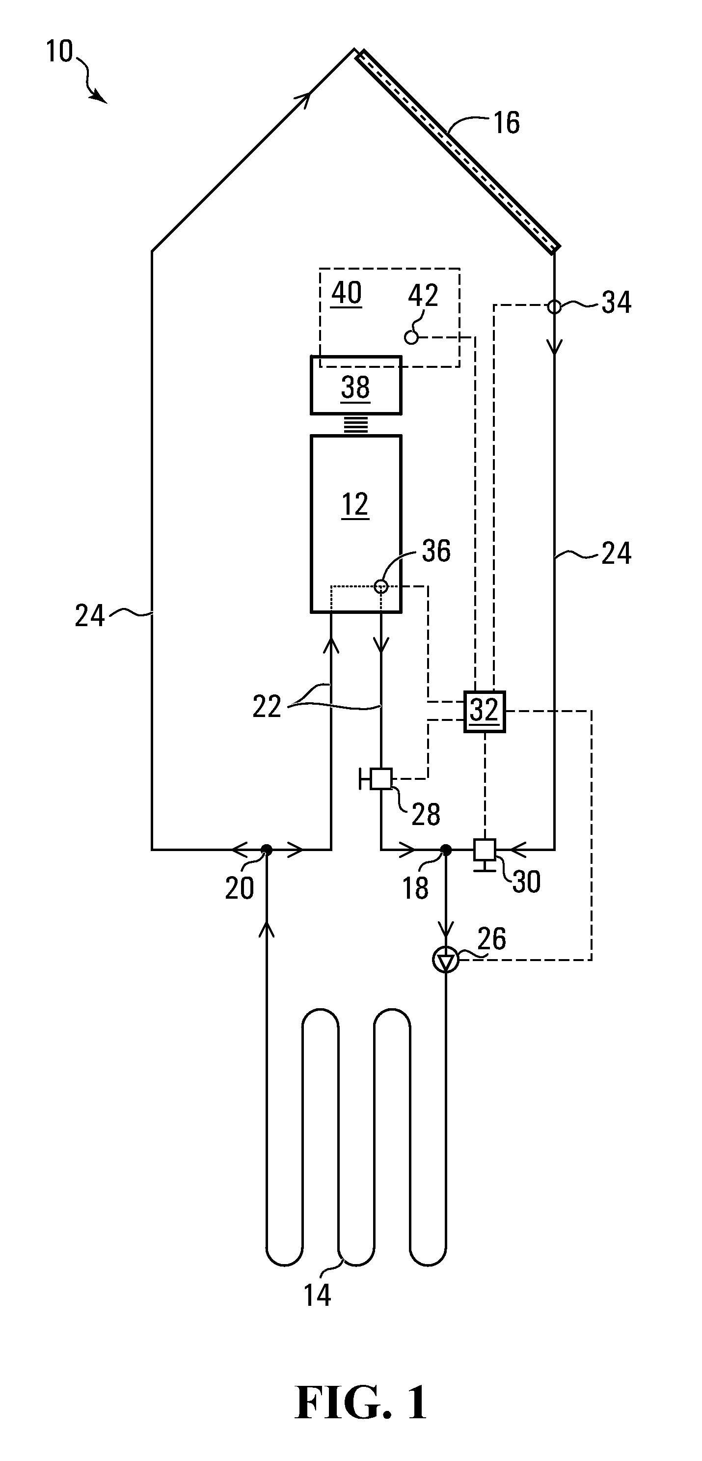
[0015]FIG. 1 shows an integrated thermal energy system 10, exemplary of an embodiment of the present invention. System 10 includes a heat pump 12 that provides heating / cooling, a ground loop 14, and a solar energy collector 16. Ground loop 14 has an inlet 18 and an outlet 20. A conduit 22 extends from in outlet 20 to heat pump 12 and from heat pump 12 back to inlet 18. A conduit 24 extends from outlet 20 to solar energy collector 16 and from solar energy collector 16 back to inlet 18. A fluid pump 26 is located in ground loop 14. A valve 28 is provided in conduit 22 and a valve 30 is provided in conduit 24.

[0016] Heat pump 12 may be any suitable heat pump and may be a conventional geothermal heat pump or ground source heat pump. For example, heat pump 12 may operate in two possible modes, a heating mode and a cooling mode, depending on demand. Heat pump 12 may also be turned off when no service is required. In the heating mode, thermal energy needs to be supplied to heat pump 12 su...


PUM


Abstract

A thermal energy system includes a solar energy collector, a ground loop having an inlet and an outlet, and a heat pump. A first fluid conduit extends from the outlet to the solar energy collector, and from the solar energy collector to the inlet, for transporting a heat exchange fluid, from the outlet to the inlet through the solar energy collector. A second fluid conduit extends from the outlet to the heat pump, and from the heat pump to the inlet, for transporting the heat exchange fluid, from the outlet to the inlet through the heat pump. A fluid pump is provide for urging the fluid to flow from the inlet to the outlet through the ground loop, and from the outlet to the inlet through at least one of the first and second conduits. Control valves and a controller may be provided to automatically select a fluid flow mode from a number of selectable modes.

Description

CROSS REFERENCE TO RELATED APPLICATIONS [0001] This applications claims the benefits of related U.S. Provisional Application Ser. No. 60 / 776,225, filed Feb. 24, 2006, the contents of which are incorporated herein by reference.FIELD OF THE INVENTION [0002] The present invention relates to integrated thermal energy systems. BACKGROUND OF THE INVENTION [0003] Geothermal systems are useful for providing the energy needs of a building, such as heating, cooling and air conditioning. A typical geothermal system includes a geothermal heat pump, and a ground loop connected to heat pump. On the one hand, ground loop exchanges heat with the earth (either the ground or a large water body such as a lake), where the earth acts as both a heat source and a heat sink. On the other hand, ground loop supplies or removes heat from heat pump depending on its mode of operation. Thus, a geothermal system can efficiently utilize natural sources of energy, such as the thermal energy stored in the earth, and...

Claims


Application Information

Patent Timeline
Patent Type & Authority Applications(United States)
IPC IPC(8): F25D17/00F25B27/00F25D23/12F25B13/00
CPCF25B27/002F25B2313/002F25B30/06
Inventor LEWKOWITZ, MICHAEL ALEXANDER BALDWINORR, DERRALMITCHELL, CHRIS
Owner LEWKOWITZ MICHAEL ALEXANDER BALDWIN
Why Eureka
Try Eureka