Engine having multiple injector locations

a technology of injector location and engine, which is applied in the direction of machines/engines, mechanical equipment, electric control, etc., can solve the problems of air-fuel ratio error, overall air-fuel ratio may be too rich, and air-fuel ratio may be temporarily too lean, so as to improve the control of air-fuel ratio

Inactive Publication Date: 2007-09-20
FORD GLOBAL TECH LLC
View PDF7 Cites 20 Cited by
  • Summary
  • Abstract
  • Description
  • Claims
  • Application Information

AI Technical Summary

Benefits of technology

[0006] In this way, it is possible to adjust fuel injection of the first and / or second injectors during transitions to account for the differences in transient performance of different injector locations, and thereby better maintain air-fuel ratio control. For example, when decreasing injection from the second injector (and possibly increasing injection from the first injector), total fuel injection can be temporarily decreased to account for fuel stored in the intake manifold. Likewise, when increasing injection from the second injector (and possibly decreasing injection from the first injector), total fuel injection can be temporarily increased to account for fuel that will be stored in the intake manifold.

Problems solved by technology

However, the inventors herein have recognized a problem with the above approaches relating to the transient responses among the different injection locations.
Thus, when changing or transitioning injection among different locations, errors in air-fuel ratio may result due to filling or emptying of fuel stored within the manifold, on manifold walls, and puddles at intake ports.
In one particular example, when changing allocation from auxiliary injection to direct injection, the overall air-fuel ratio may be too rich due to residual fuel in intake manifold being pulled into the cylinder even after auxiliary injection is stopped or reduced.
Likewise, when changing to increase or begin auxiliary injection, the air-fuel ratio may be temporarily too lean due to losses of fuel from auxiliary injector to manifold surfaces and filling the manifold with air-fuel mixture.

Method used


Image

  • Engine having multiple injector locations
  • Engine having multiple injector locations
  • Engine having multiple injector locations

Examples


Embodiment Construction

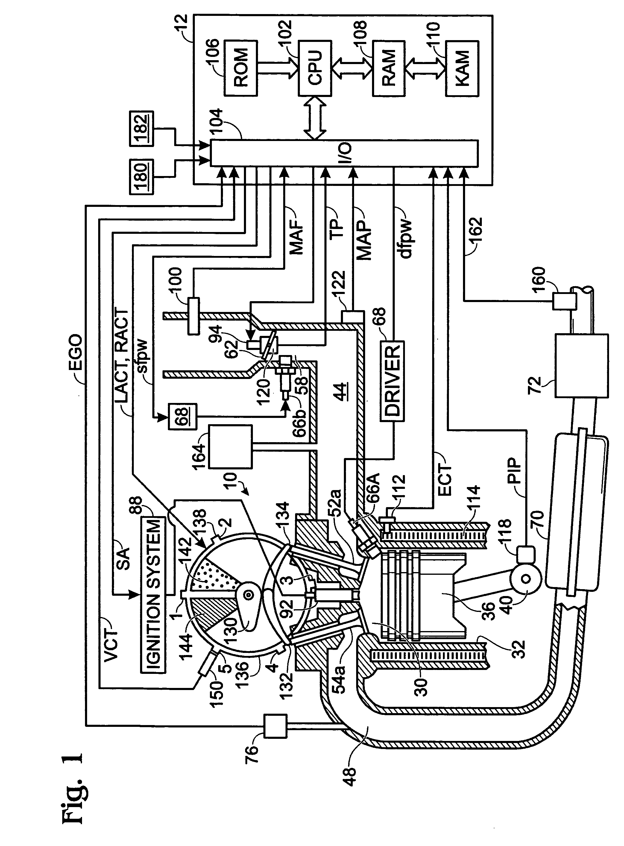
[0012]FIG. 1 shows one cylinder of a multi-cylinder engine, as well as the intake and exhaust path connected to that cylinder. In the embodiment shown in FIG. 1, engine 10 is capable of using different injector locations in one example. The injectors in different locations may be different sized injectors, operate at different fuel pressures, or have other different operating parameters.

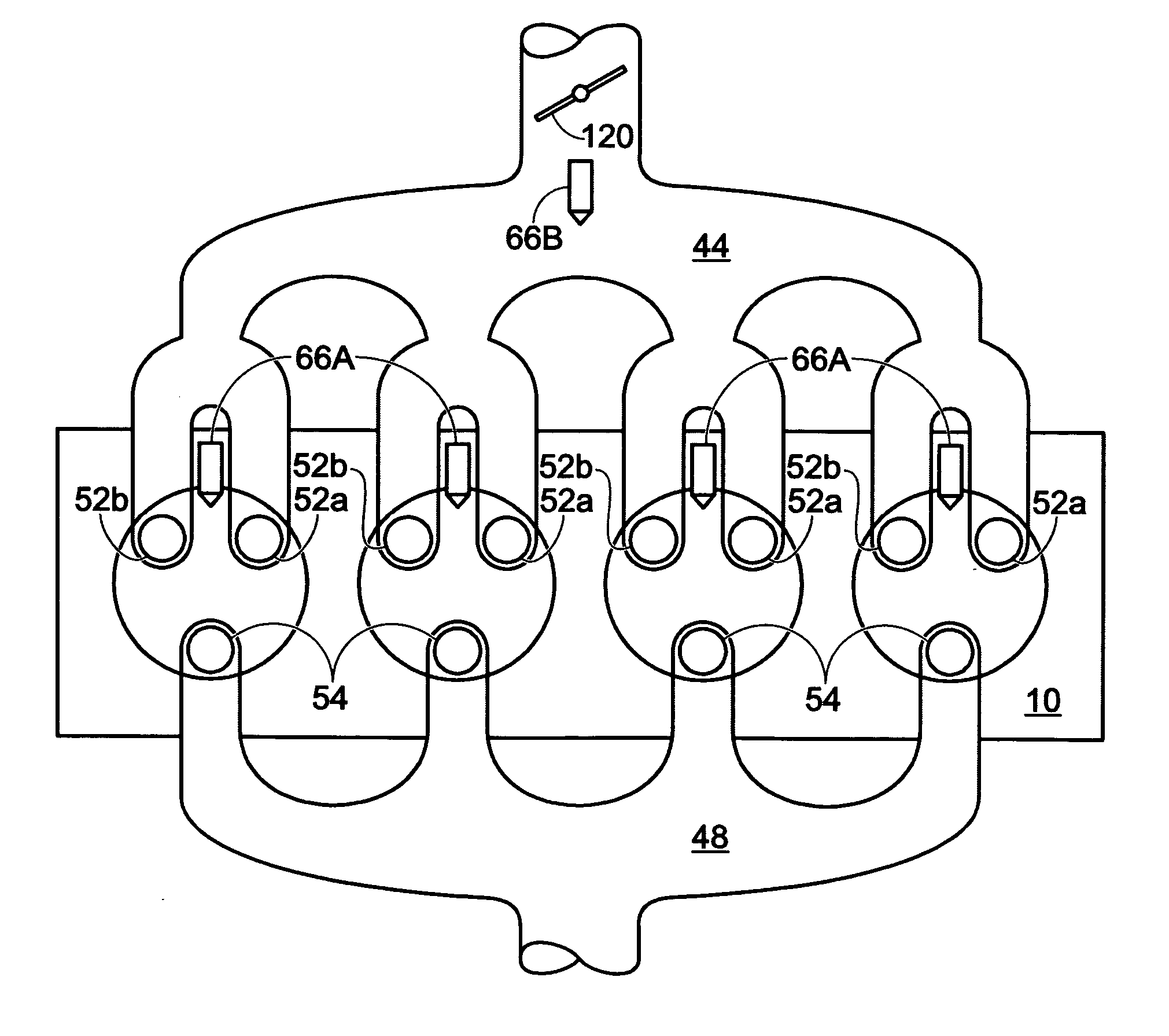
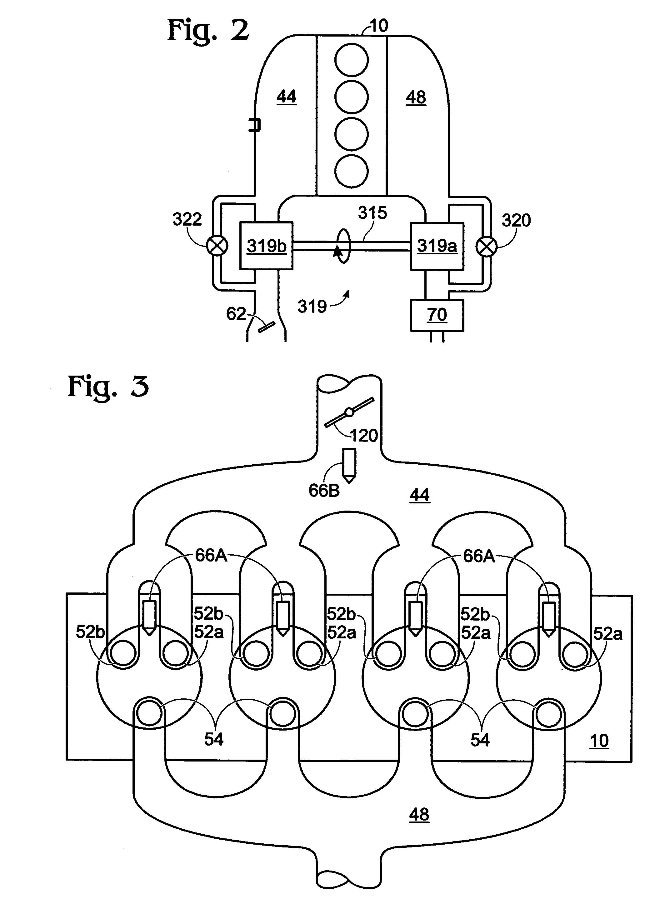
[0013]FIG. 1 shows one example fuel system with a direct fuel injector in each cylinder, and a supplemental injector for delivering fuel to more than one cylinder. The supplemental injector may be configured in various locations, such as in the intake manifold, in the throttle body, or others as described in more detail below herein.

[0014] Continuing with FIG. 1, it shows a dual injection system, where engine 10 has both direct and supplemental fuel injection, as well as spark ignition. Internal combustion engine 10, comprising a plurality of combustion chambers, is controlled by electronic engine ...


PUM


Abstract

A method for controlling a first and second injector of an engine, the first injector located in a first cylinder of the engine and the second injector located upstream of, and configured to inject fuel into, the first and a second cylinder of the engine, the method comprising of decreasing total injection from the first and second injectors when decreasing injection from the second injector, and increasing total injection from the first and second injectors when increasing injection of the second injector.

Description

BACKGROUND AND SUMMARY [0001] Vehicle engines have utilized various forms of carburetion and fuel injection. For example, one type of fuel injection that may be used is port injection, where each cylinder of the engine has an injector in the cylinder intake port, sometimes referred to as multi-port fuel injection. Another type of fuel injection that may be used is direct cylinder injection, in which each cylinder of the engine has an injector coupled in the cylinder (either overhead or side-mounted) for injecting fuel directly into the cylinder. Still another type of fuel injection that may be used is central, or throttle body, injection, where a centrally located fuel injector delivers fuel into an intake manifold that feeds a plurality of cylinders. [0002] In some examples, engine may use multiple types of injection in an engine to achieve various results. For example, as described in U.S. Pat. No. 6,786,201 or U.S. Pat. No. 5,924,405, direct injection with a sub-injector, or auxi...

Claims


Application Information

Patent Timeline
Patent Type & Authority Applications(United States)
IPC IPC(8): F02B7/00F02B17/00F02B3/00F02D7/00
CPCF02B17/005F02D17/02F02D19/0631F02D19/081F02D19/12F02D19/0694F02D41/3845F02M69/046Y02T10/36F02D19/061F02D19/0692F02D41/3094F02D41/047Y02T10/30
Inventor BREHOB, DIANALEWIS, DONALD J.HOARE, GRAHAM
Owner FORD GLOBAL TECH LLC
Why Eureka
Try Eureka