Fixing device for a fuel injection valve

a technology of fuel injection valve and fixing device, which is applied in the direction of fuel injection apparatus, machine/engine, feed system, etc., can solve the problems of inability to reliably prevent, no longer precisely centrally introduced contact pressure into the fuel injection valve, and affecting the function of the moving parts of the fuel injection valv

Inactive Publication Date: 2004-03-04
VODAFONE GRP PLC +1
View PDF7 Cites 5 Cited by
  • Summary
  • Abstract
  • Description
  • Claims
  • Application Information

AI Technical Summary

Benefits of technology

[0003] The fastening device of the invention for a fuel injection valve has the advantage that the fastening force is always exerted symmetrically on the fuel injection valve, so that the fastening device does not exert any tilting moment, or at most only a very slight tilting moment. To that end, a support point is embodied on the fuel injection valve and forms a straight line, which is located in the same plane as the longitudinal axis of the fuel injection valve. As a result, the fastening force is introduced into a plane of symmetry of the fuel injection valve. The clamping jaw has a support face, which in the event of a horizontal shift, that is, perpendicular to the longitudinal axis of the fuel injection valve, slides across the support point, so that the point where the fastening force is introduced into the fuel injection valve remains fixed.[0004] In an advantageous feature of the subject of the invention, the support face on the clamping jaw is embodied in planar form, so that it can easily slide along the linear support point of the fuel injection valve.[0005] In a further advantageous feature, the clamping jaw is embodied as a two-armed lever, on one end of which the support face is embodied and the other end of which rests at least indirectly on the cylinder head, and the fastening force is introduced between the two ends of the clamping jaw. As a result of this embodiment, the already known clamping jaw can be used for the fastening device of the invention, with a slight modification of the support face.[0006] In an advantageous feature, the linear support point on the fuel injection valve is a ridge which is formed by two chamfers. As a result of this embodiment, the linear support point can be manufactured simply.[0007] In another advantageous feature, two support points diametrically opposed to one another relative to the longitudinal axis are embodied on the fuel injection valve, each embodied as a ridge formed by two chamfers. As a result, the fastening force can be introduced symmetrically on two sides of the fuel injection valve. This is especially advantageous if, on the end where the support face is located, the clamping jaw is embodied as forked.[0008] In a further advantageous feature, the support point on the fuel injection valve is embodied as a jacket line of a support cylinder, whose longitudinal axis intersects the longitudinal axis of the fuel injection valve. This has the advantage that the clamping jaw, if it shifts horizontally, rolls with its support face over the cylinder and thus cannot exert any horizontal forces on the fuel injection valve. As a result, any tilting moments on the fuel injection valve that still occur are reduced still further. It can also advantageously be provided that two support cylinders be disposed coaxially in line with one another, each on one side of the fuel injection valve.

Problems solved by technology

However, this cannot always be reliably prevented in the construction shown there: Thermal expansion of the clamping jaw or other parts of the engine, or shaking or shifting, can cause the support face of the clamping jaw to shift on the fuel injection valve, so that the contact pressure is no longer introduced precisely centrally into the fuel injection valve in the direction of the longitudinal axis.
The result can be a tilting moment of the fuel injection valve in the bore and hence an uneven mechanical load, which can impair the function of the moving parts in the fuel injection valve considerably.
This fastening device likewise has the disadvantage that the contact pressure does not always act centrally on the fuel injection valve, so that as already described, a tilting moment on the fuel injection valve can occur, with the attendant disadvantages.

Method used


Image

  • Fixing device for a fuel injection valve
  • Fixing device for a fuel injection valve
  • Fixing device for a fuel injection valve

Examples


Embodiment Construction

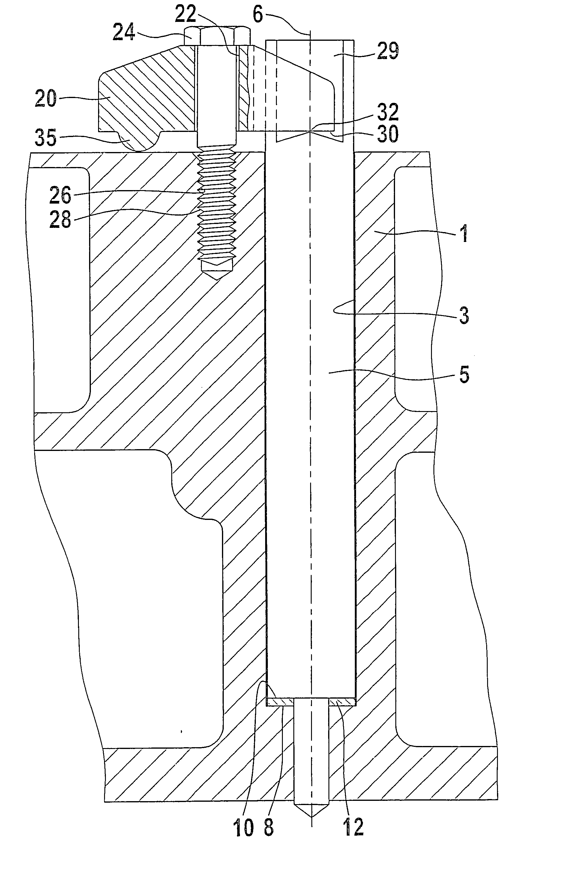
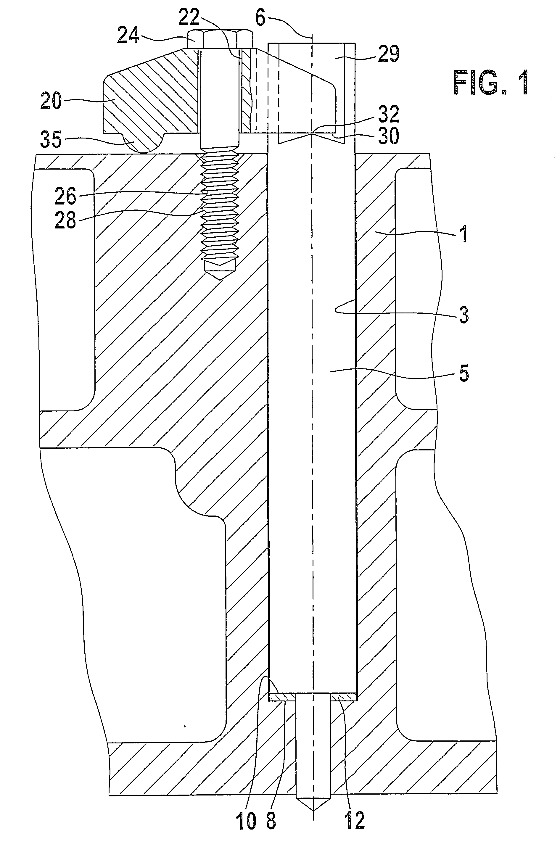
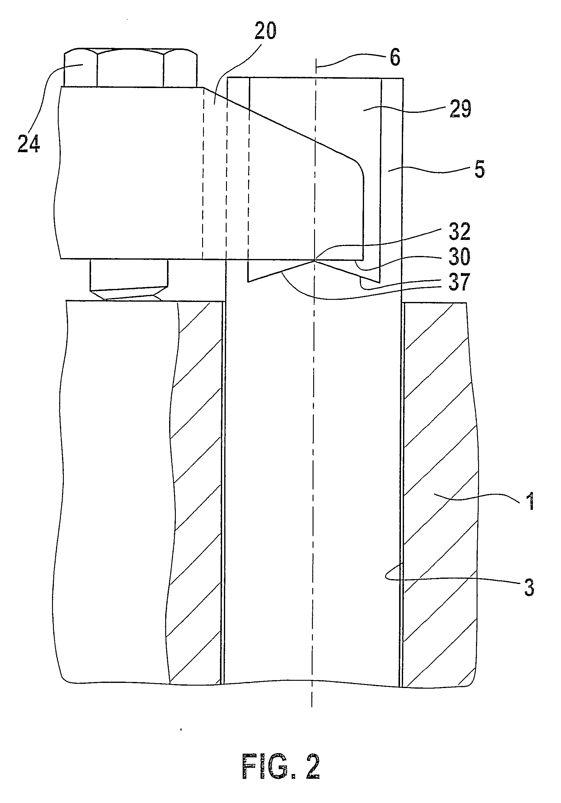
[0015] In FIG. 1, a longitudinal section through the cylinder head of an internal combustion engine is shown. In the cylinder head 1 of the engine, which is not otherwise shown, there is a bore 3, which is embodied in stepped form, forming an annular step 8, the annular step 8 being oriented toward the combustion chamber. A fuel injection valve 5 is disposed in the bore 3; it has a longitudinal axis 6, and on its outer jacket face, an annular shoulder 10, with which the fuel injection valve 5 rests, with the interposition of a sealing disk 12, on the annular step 8 of the bore 3. On the substantially cylindrically embodied end, remote from the combustion chamber, of the fuel injection valve 5, two diametrically opposed flat faces 29, 29' are embodied. For the sake of simplification, the connections for the fuel and other connections of the fuel injection valve 5 are not shown in the drawing.

[0016] A clamping jaw 20, which is embodied as a two-armed lever, is disposed on the side of ...


PUM


Abstract

A fastening device for a fuel injection valve (5) in a bore (3) in the cylinder head of an internal combustion engine, in which the fuel injection valve (5) has a longitudinal axis (6). A clamping jaw (20) is acted upon by a fastening force, and the clamping jaw (20) rests with at least one support face (30) on a support point (32) of the fuel injection valve (5), so that the clamping jaw (20) is pressed with its support face (30) against the support point (32). The support point (32) on the fuel injection valve (5) is embodied linearly, and the line is straight and in its imaginary extension intersects the longitudinal axis (6) of the fuel injection valve (5)

Description

PRIOR ART[0001] The invention is based on a fastening device for a fuel injection valve as defined generically by the preamble to claim 1. One such fastening device is known for instance from German Patent DE 195 21 363 C1. In the fastening device shown there, a fuel injection valve is fastened in a bore in the cylinder head of an internal combustion engine, and the fuel injection valve, which has a longitudinal axis, is secured with a clamping jaw. The clamping jaw has a support face, with which it rests on a support point of the fuel injection valve. The clamping jaw is acted upon in its center by a fastening force, and the fastening force is exerted by a screw that presses the clamping jaw against the cylinder head. By means of the fastening force, the clamping jaw is pressed with its support face against the support point of the fuel injection valve and presses the fuel injection valve into the bore in the cylinder head. In DE 195 21 363 C1, the support face of the clamping jaw ...

Claims


Application Information

Patent Timeline
Patent Type & Authority Applications(United States)
IPC IPC(8): F02M61/14
CPCF02M61/14
Inventor HEINRICH, PETER
Owner VODAFONE GRP PLC
Why Eureka
Try Eureka