
Guide tape

a technology of guide tape and tape, which is applied in the direction of metal working equipment, chemistry apparatus and processes, and lamination ancillary operations, etc., can solve the problems of difficult to precisely follow the straight edge, undesirable or difficult to draw such a line, and difficult to cut a straight line on a work piece such as paper, cardstock, fabric etc., and achieve the effect of facilitating measuring distances

Inactive Publication Date: 2007-09-20
PROCESS4
View PDF6 Cites 2 Cited by
  • Summary
  • Abstract
  • Description
  • Claims
  • Application Information

AI Technical Summary

Benefits of technology

The present invention provides adhesive tape with guide elements for cutting a work piece, as well as length measurement indicia for measuring distances on the work piece. The tape is designed to provide a straight line when adhered to a work piece and includes a longitudinally extending linear indicia. The technical effects of the invention include improved accuracy and efficiency in cutting and measuring distances on a work piece.

Problems solved by technology

Cutting a straight line on a work piece such as paper, cardstock, fabric etc. with a pair of scissors or a knife is difficult.
However, depending on the type or work piece and ultimate purpose of the work piece, it may be undesirable or difficult to draw such a line.
However, it is frequently difficult to follow the straight edge exactly.
It is also difficult to accurately reposition the straight edge if the cut line is longer than the straight edge, or if the straight edge is shifted during use.
Furthermore, when a user uses his / her own hand to hold down the straight edge, the knife's blade comes close to the user's fingers, which increases the possibility of cutting the user's fingers if his / her fingers or the knife blade slip.

Method used


Image

  • Guide tape
  • Guide tape
  • Guide tape

Examples


Embodiment Construction

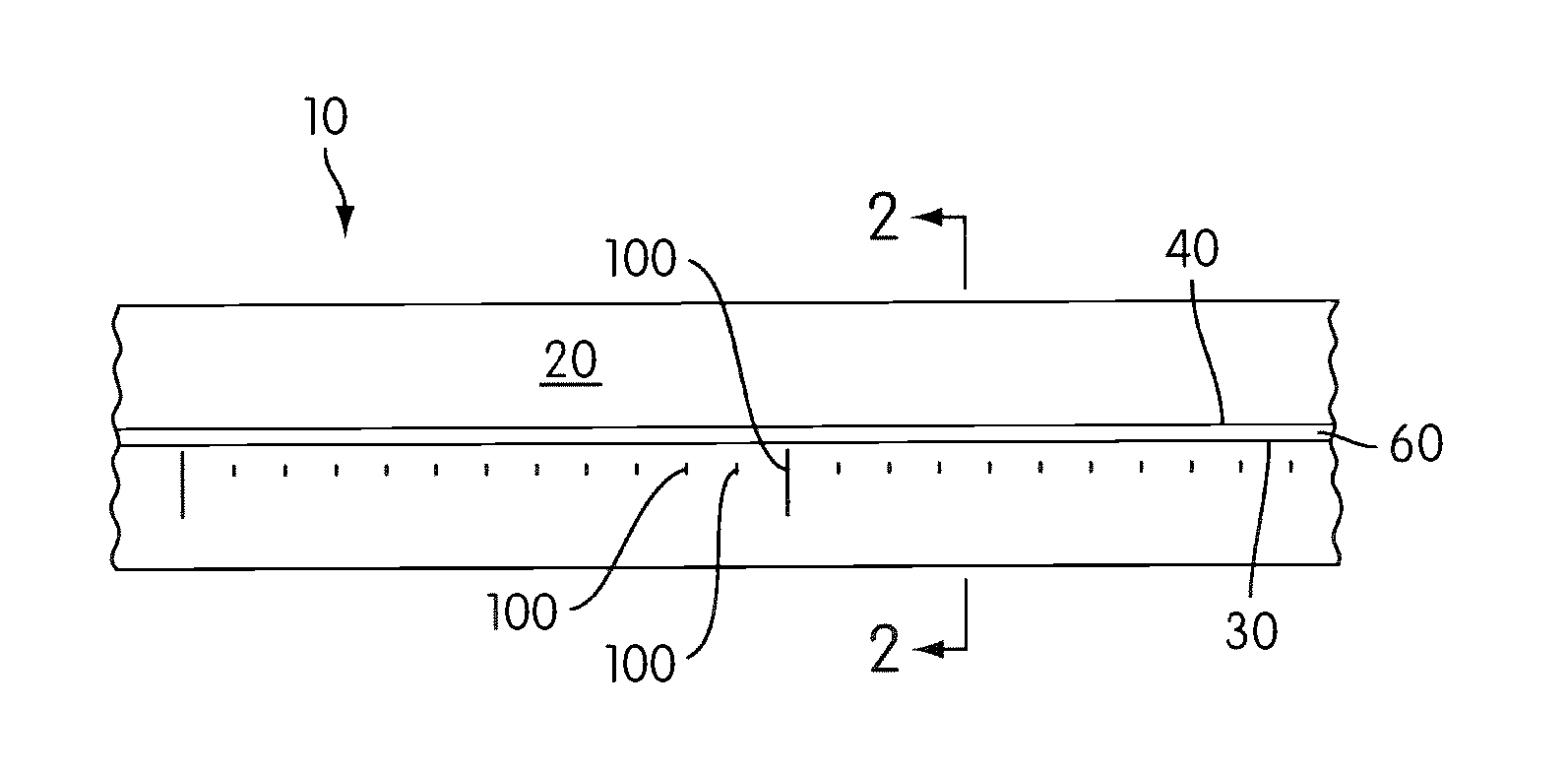
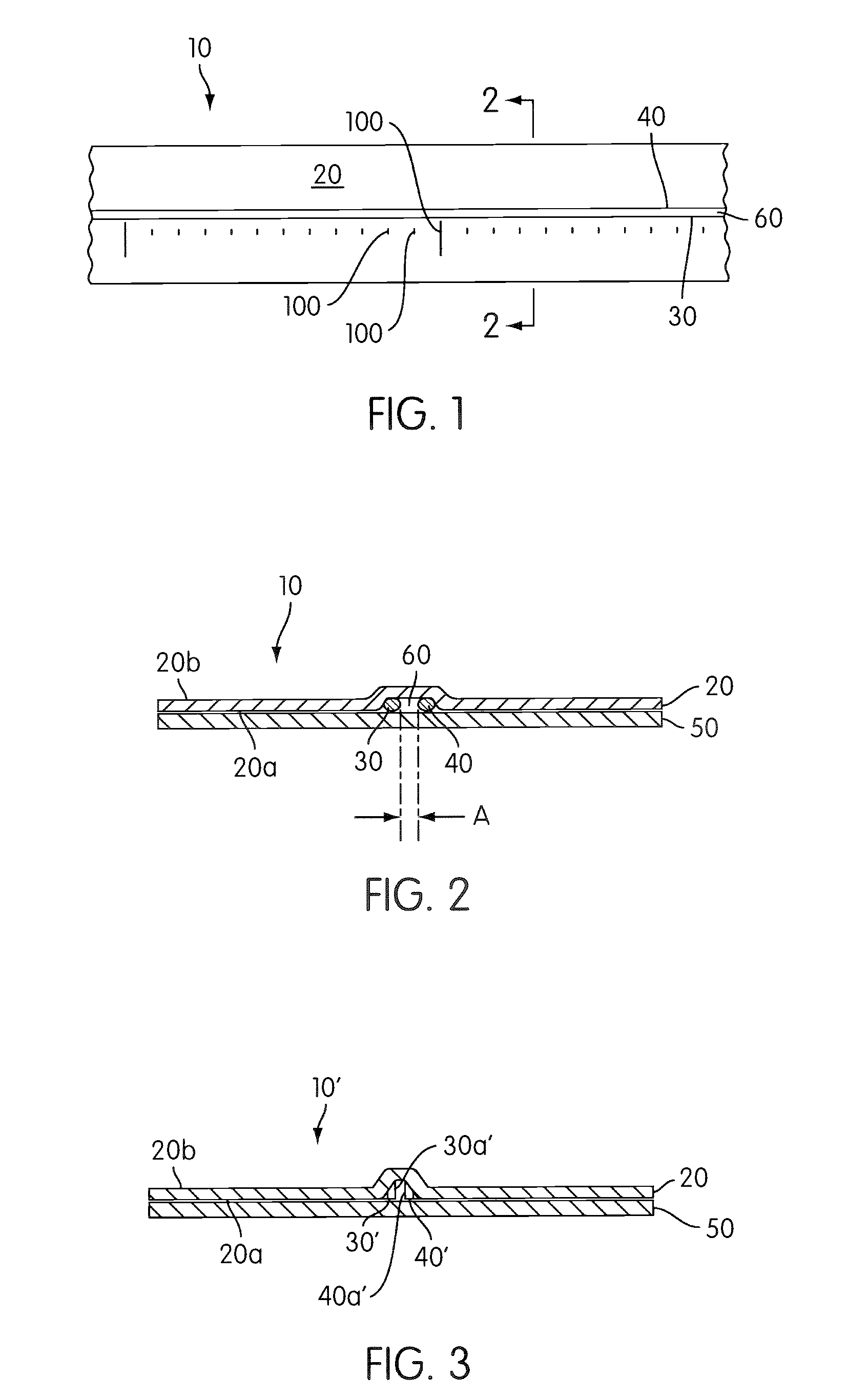
[0023]FIGS. 1 and 2 illustrate guide tape 10 according to an embodiment of the present invention. The guide tape 10 comprises adhesive tape 20 and two guide wires 30, 40 (or guide elements). The guide tape 10 may be releasably adhered to a release liner 50.

[0024] The adhesive tape 20 includes an adhesive side 20a. The adhesive tape 20 may be clear like transparent packaging tape, or opaque like masking tape. The adhesive side 20a preferably has a repositionable adhesive, but may alternatively include any other suitable type of adhesive. The adhesive tape 20 may comprise a thin, flexible material such as oriented polypropylene or other thermoplastic. The adhesive tape 20 may be conventional packaging tape. The adhesive tape 20 is preferably thin enough that it may be easily cut in either the longitudinal or transverse direction using a cutting device such as a knife blade or pair of scissors. According to various embodiments of the present invention, the adhesive tape may be less th...


PUM

PropertyMeasurementUnit
thickaaaaaaaaaa
thickaaaaaaaaaa
thickaaaaaaaaaa

Abstract

A cutting guide includes an adhesive tape and two longitudinally-extending parallel guide elements connected to the adhesive tape. The guide tape may be adhered to a work piece to help guide a cutting device along a straight or curved cutting path defined between the wires.

Description

CROSS REFERENCE TO RELATED APPLICATIONS [0001] The present application claims the benefit of U.S. provisional application No. 60 / 775,341, filed Feb. 22, 2006, and is hereby incorporated in its entirety by reference.BACKGROUND OF THE INVENTION [0002] 1. Field of the Invention [0003] The present invention relates to devices and methods for making straight cuts, scores, and / or marks on work pieces. [0004] 2. Description of Related Art [0005] Cutting a straight line on a work piece such as paper, cardstock, fabric etc. with a pair of scissors or a knife is difficult. People frequently first draw a straight line on the work piece to guide subsequent cutting. However, depending on the type or work piece and ultimate purpose of the work piece, it may be undesirable or difficult to draw such a line. [0006] A straight edge (e.g., a straight-edged ruler) is sometimes used in conjunction with a knife to guide the knife's blade along a straight line. However, it is frequently difficult to follo...

Claims


Application Information

Patent Timeline
Patent Type & Authority Applications(United States)
IPC IPC(8): B32B38/04B32B37/12
CPCB26B29/06Y10T156/108Y10T156/1052
Inventor TAYLOR, CURTIS PATRICKMIKA, STEPHEN EDWARD
Owner PROCESS4
Learn More