Fastening device for mounting an electrical fixture

a technology for fastening devices and electrical fixtures, which is applied in the direction of coupling devices, machine supports, electrical apparatus casings/cabinets/drawers, etc., can solve the problems of not having both hands free to perform installation tasks, awkward and cumbersome tasks, etc., and achieves the effect of easy pulling out and removing the overlay

Inactive Publication Date: 2007-09-20
ANGELO FAN BRACE LICENSING
View PDF14 Cites 1 Cited by
  • Summary
  • Abstract
  • Description
  • Claims
  • Application Information

AI Technical Summary

Benefits of technology

[0011]The overlay also includes a group of incisions that allow an installer to easily pull-out and remove the overlay after tightening all of the preset fasteners. The incisions surround each preset fastener opening. When an installer tightens the preset fastener, the incisions allow the overlay to open...

Problems solved by technology

The installation of the mounting bracket assembly to the two spaced beams, joists, studs, or the like and the installation of the electrical junction box directly to the beam, joist, stud, cross-member, o...

Method used


Image

  • Fastening device for mounting an electrical fixture
  • Fastening device for mounting an electrical fixture
  • Fastening device for mounting an electrical fixture

Examples


Embodiment Construction

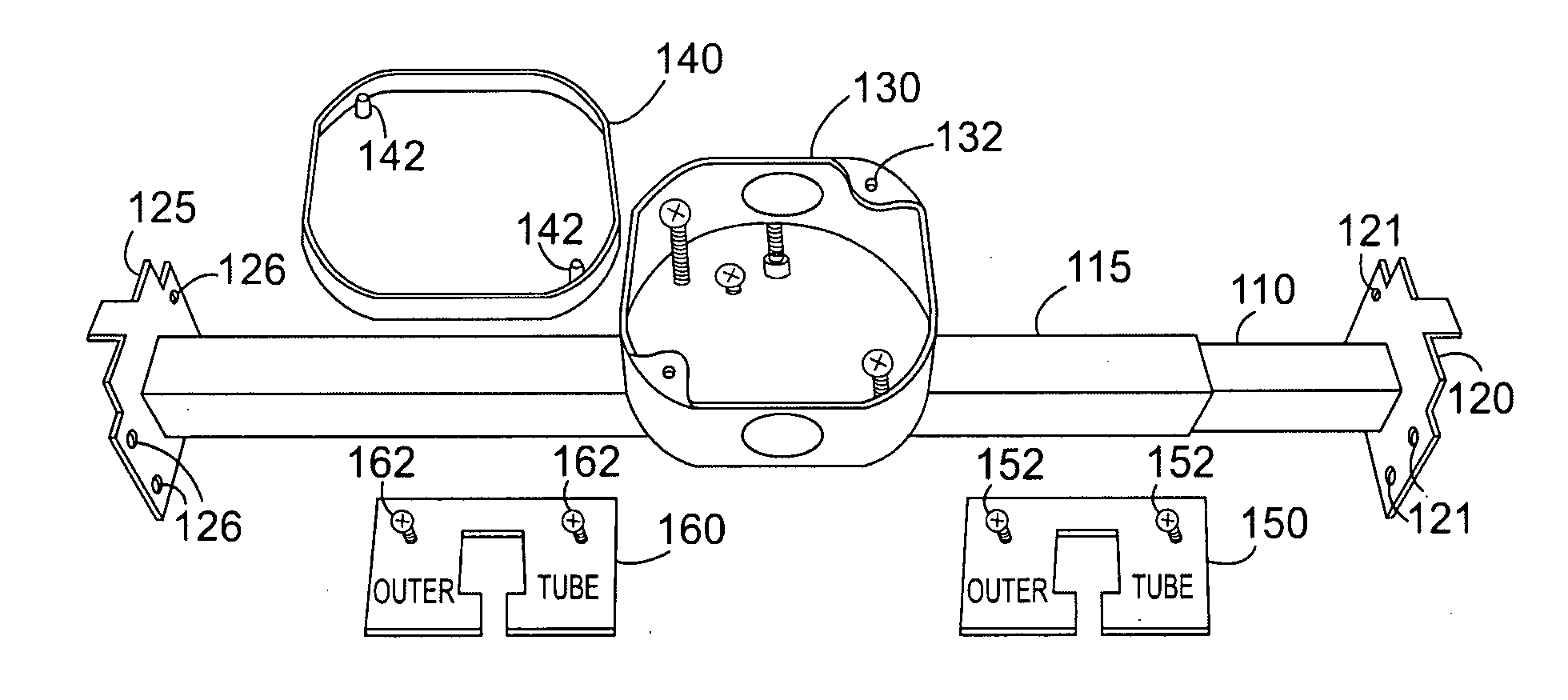
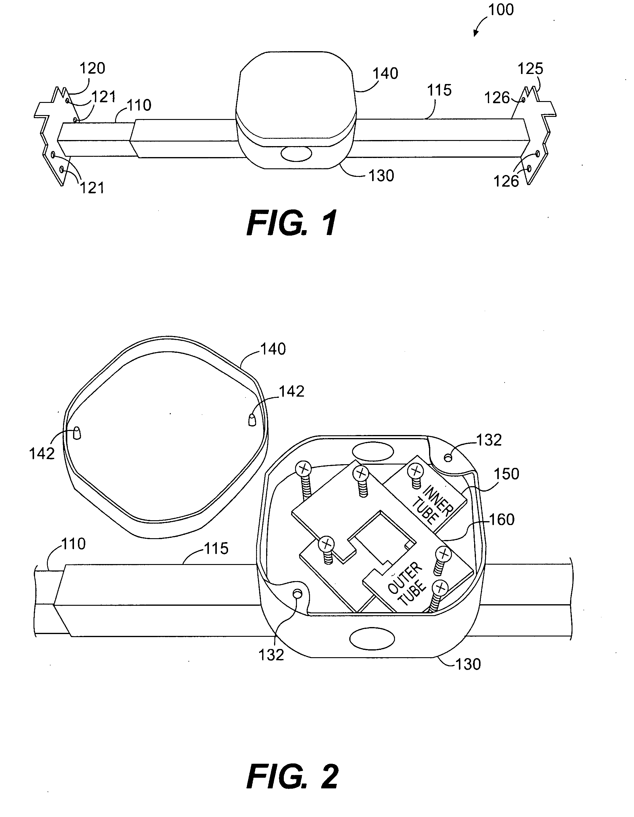
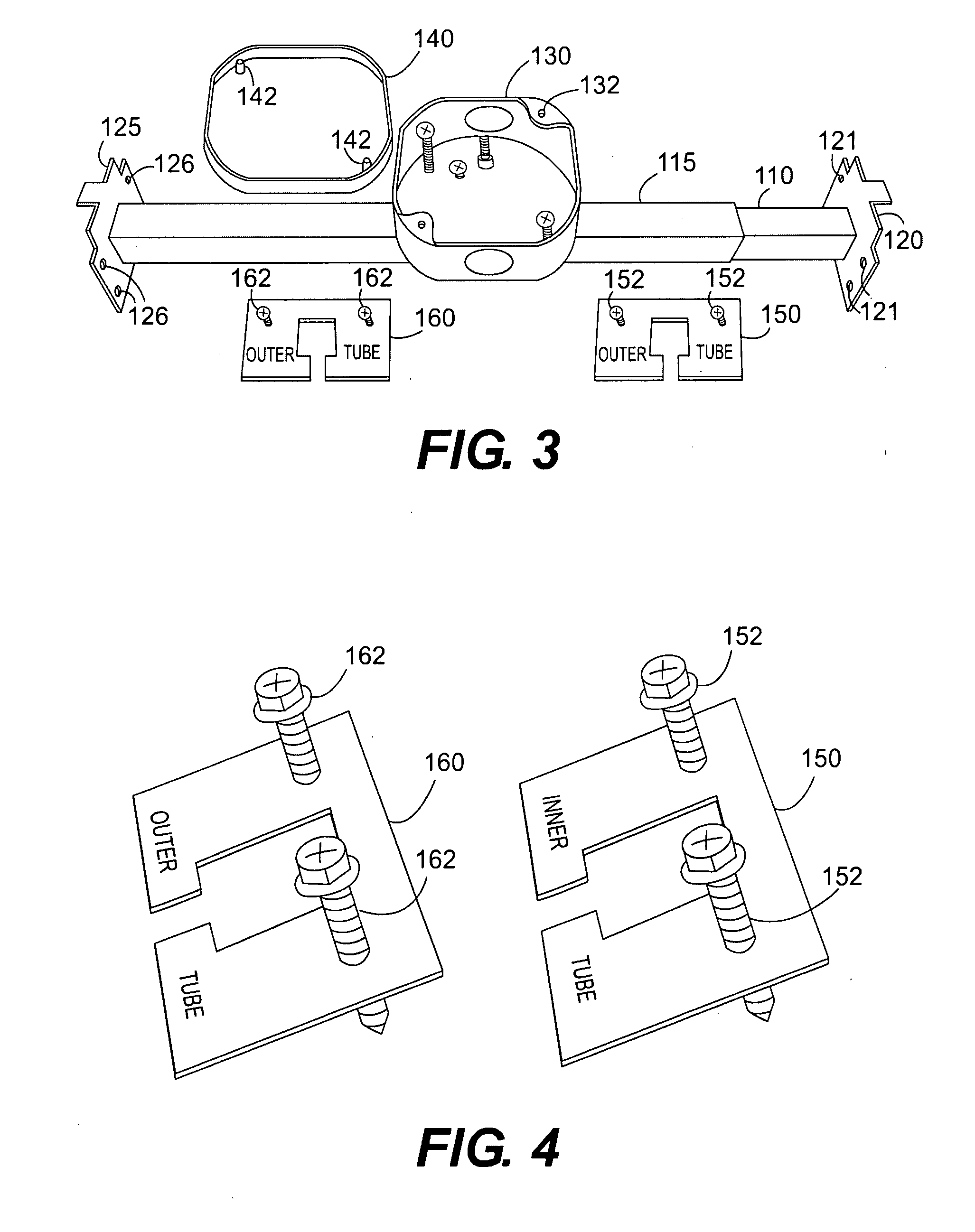
[0026]FIGS. 1-8 illustrate an assembly for mounting an electrical fixture with an exemplary embodiment of a fastening device of the present invention.

[0027]As shown in FIG. 1, the mounting bracket assembly 100 includes a telescoping tubular bar mechanism having an inner member 110 and an outer member 115, an end-plate 120 attached to the inner member 110, and an end-plate 125 attached to the outer member 115, a metal electrical junction box 130 attached to the telescoping tubular bar mechanism, and a plastic cover 140 over the electrical junction box 130. The end-plates 120, 125 include openings 121, 126 that receives fasteners to attach the end-plates 120, 125 to a joist or beam (not shown). The diameter of the inner member 110 is smaller than the diameter of the outer member 115 to allow the inner member 110 to slide inside the outer member 115, thereby producing the telescoping nature of the tubular bar mechanism. The attachment of the electrical junction box 130 to the telescopi...


PUM


Abstract

A fastening device for mounting an electrical fixture suspended from an electrical junction box in a ceiling. When a mounting bracket assembly suspends the electrical junction box between two joists, the fastening device is an overlay positioned adjacent to each end-plate of the support bar. When the electrical junction box attaches directly to a joist, the fastening device is an overlay positioned inside a cavity of the electrical junction box. The overlay includes fastener openings that position a preset fastener to attach the end-plates to the spaced joists, or openings in the top wall of the cavity to attach the electrical junction box to a joist in the ceiling. The overlay also includes radial incisions, cut in a star pattern, that surround each fastener opening. When an installer tightens all of the fasteners, the star patterns open and allow the installer to easily pull-out and remove the overlay.

Description

CROSS-REFERENCE TO A RELATED APPLICATION[0001]This application for letters patent is related to and incorporates by reference provisional application for patent Ser. No. 60 / 783,410, titled “Fastening Device for Mounting an Electrical Fixture” and filed in the United States Patent and Trademark Office on Mar. 20, 2006.BACKGROUND OF THE INVENTION[0002]1. Field of the Invention[0003]This invention relates to a fastening device for mounting an electrical fixture. In particular, the invention is a fastening device for mounting an electrical fixture in a ceiling area.[0004]2. Description of the Prior Art[0005]An electrical junction box provides a safe enclosure for the electrical wiring that powers an electrical fixture. For an electrical fixture hanging from a ceiling, such as a ceiling fan or light fixture, the electrical junction box typically spans between two spaced beams, joists, studs, or the like. A mounting bracket assembly provides the support necessary to suspend the electrical...

Claims


Application Information

Patent Timeline
IPC IPC(8): H01H13/04
CPCH02G3/20H02G3/125Y10S248/906
Inventor KERR, JACK RUSSELL
Owner ANGELO FAN BRACE LICENSING
Why Eureka
Try Eureka