Yarn package supporting bracket for use on a creel

Inactive Publication Date: 2007-09-20
ZOLLINGER RICHARD V
View PDF12 Cites 16 Cited by
  • Summary
  • Abstract
  • Description
  • Claims
  • Application Information

AI Technical Summary

Benefits of technology

[0005] The present invention provides a yarn package supporting bracket that provides precise and consistent positioning of a yarn package on a creel in position for yarn feeding so that yarn will be fed from the yarn package uniformly without significant tension variations that result from positioning variations when using prior art yarn package supports.
[0006] Briefly described, the yarn package supporting bracket of the present invention has an attaching portion that attaches the bracket to a creel for movement of the bracket between a yarn feeding position and a package loading position. One of the creel and bracket has a magnetically attractable portion and the other has a magnet thereon engagable with the magnetically attractable portion to releaseably fix the bracket and a yarn package supported thereon in a yarn feeding position. This magnetic fixing of the position of the bracket provides precise and repeatable positioning that is not possible with prior art brackets that require tolerances and other potential misalignment factors.

Problems solved by technology

Because there must be some tolerance in the complimentary dimension of the pin and recess, and because there can be imprecise positioning of the fixed portion by the set screw, precise and truly fixed positioning of the yarn package in the yarn feeding position is not uniformly accomplished, resulting in potential variations in the tension of the yarn being fed and resulting various in uniformity in the fabric being produced.

Method used


Image

  • Yarn package supporting bracket for use on a creel
  • Yarn package supporting bracket for use on a creel
  • Yarn package supporting bracket for use on a creel

Examples


Embodiment Construction

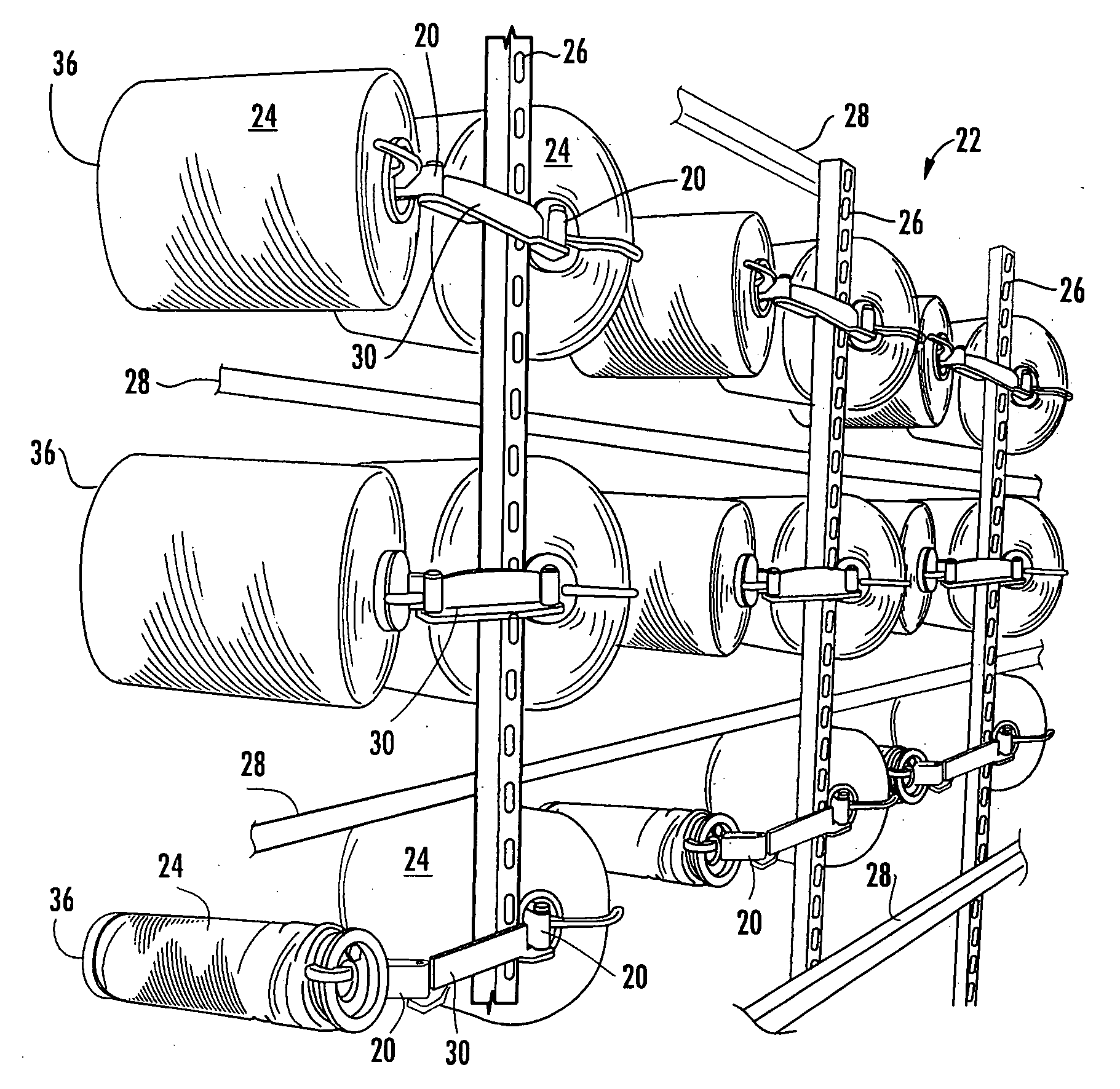
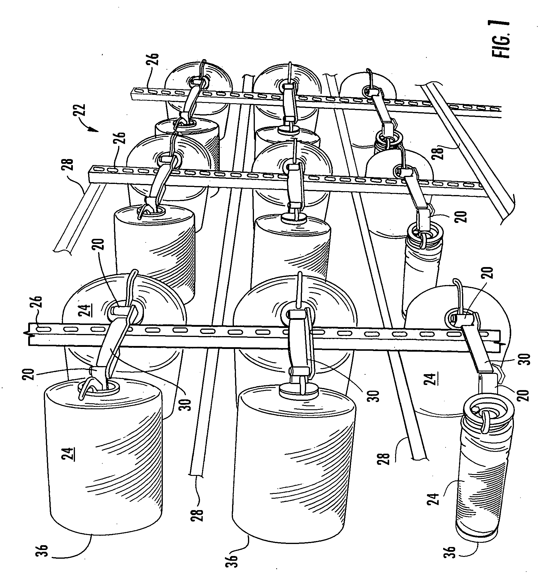
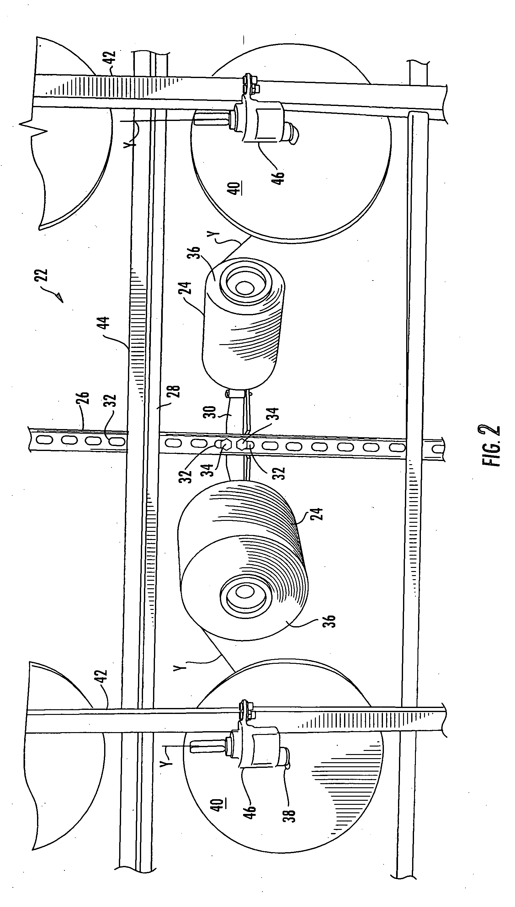
[0020] Referring first to FIG. 1, yarn package supporting brackets 20 are shown mounted on a creel 22 with yarn packages 24 positioned in yarn feeding position. The creel 22 is a frame having vertical and horizontal frame members 26 and 28, respectively. FIG. 1 illustrates only a portion of the rear of a creel 22. Horizontally extending arms 30 are bolted to the vertical frame members 26 in selected mounting holes 32 formed in vertical rows in the vertical frame members 26 by bolts 34.

[0021] In the yarn feeding position illustrated in FIGS. 1 and 2, the yarn packages 24 have there outer faces 36 aimed toward guiding holes 38 in the balloon stopping discs 40 mounted on the vertical frame members 42 at the front of the creel 22. The vertical frame members 42 at the front of the creel 22 are stabilized by horizontal frame members attached thereto.

[0022] Yarn being fed from the yarn packages 24 travels through the holes 38 in the discs 40 and then to and through guides 46, which are p...


PUM


Abstract

A yarn package supporting bracket for use on a creel and attached to the creel for swiveling between a yarn feeding position and a yarn package loading position. The bracket has a magnet and the creel has a magnetically attractable portion with the magnet and magnetically attracted portion having flat surfaces that are in flush contact when the bracket is in yarn feeding position to releaseably fix by magnetic force the bracket and yarn package in the yarn feeding position.

Description

FIELD ON THE INVENTION [0001] The present invention relates to a yarn package supporting bracket for use on a creel, and, more particularly to a yarn package supporting bracket that is moveably mounted on a creel for positioning of a yarn package in a yarn feeding position and a yarn package loading position. BACKGROUND OF THE INVENTION [0002] Creels are commonly used in conjunction with various textile machines for feeding yarns from yarn packages mounted on the creel to adjacent textile manufacturing equipment, such as looms, tufting machines and knitting machines. Typically, yarn packages are mounted on brackets at one side of a creel with one end of a yarn package mounted on the bracket and the opposite end facing inwardly of the creel toward an eyelet or guide through which yarn is drawn from the unsupported end of the yarn package to the textile machine. Because variations in the tension of yarn being fed from a yarn package will have a corresponding effect on the uniformity, ...

Claims


Application Information

Patent Timeline
Patent Type & Authority Applications(United States)
IPC IPC(8): B65H49/14B65H67/02
CPCB65H49/16D02H1/00B65H67/02
Inventor ZOLLINGER, RICHARD V.
Owner ZOLLINGER RICHARD V
Why Eureka
Try Eureka