Systems and methods for a gas field ion microscope

a gas field ion microscope and system technology, applied in material analysis using wave/particle radiation, instruments, nuclear engineering, etc., can solve the problems of typical damage of sample by fibs, and achieve the effects of reducing diffraction effects, reducing energy spread, and superior voltage contras

Active Publication Date: 2007-09-20
ALIS CORP
View PDF58 Cites 81 Cited by
  • Summary
  • Abstract
  • Description
  • Claims
  • Application Information

AI Technical Summary

Benefits of technology

This patent describes an improved method for making microscopic images called Helium Ion Microscopy which uses a special device called an ALIGAS gas field ionization source. Compared to other methods like scanning electron microscopes (SEMs) and fiber optic based devices (FIBs), this technique has many benefits. It does not cause any damage to samples and its high-contrast imaging capabilities make it better suited for analyzing materials. Its unique properties also allow for more precise focus on specific areas of samples. Overall, this technology provides researchers with greater accuracy and precision in their analysis of tiny samples.

Problems solved by technology

The technical problem addressed in this patent text is the need for a microscope with a reliable and brighter ion source that can produce highly resolved images at close to atomic level without causing any damage to the samples being examined.

Method used


Image

  • Systems and methods for a gas field ion microscope
  • Systems and methods for a gas field ion microscope
  • Systems and methods for a gas field ion microscope

Examples


Embodiment Construction

[0022]There are other aspects and embodiments of the systems and methods of the invention will be described more fully by referring to the figures provided.

[0023]The systems and methods described herein will now be described with reference to certain illustrative embodiments. However, the invention is not to be limited to these illustrated embodiments which are provided merely for the purpose of describing the systems and methods of the invention and are not to be understood as limiting in anyway.

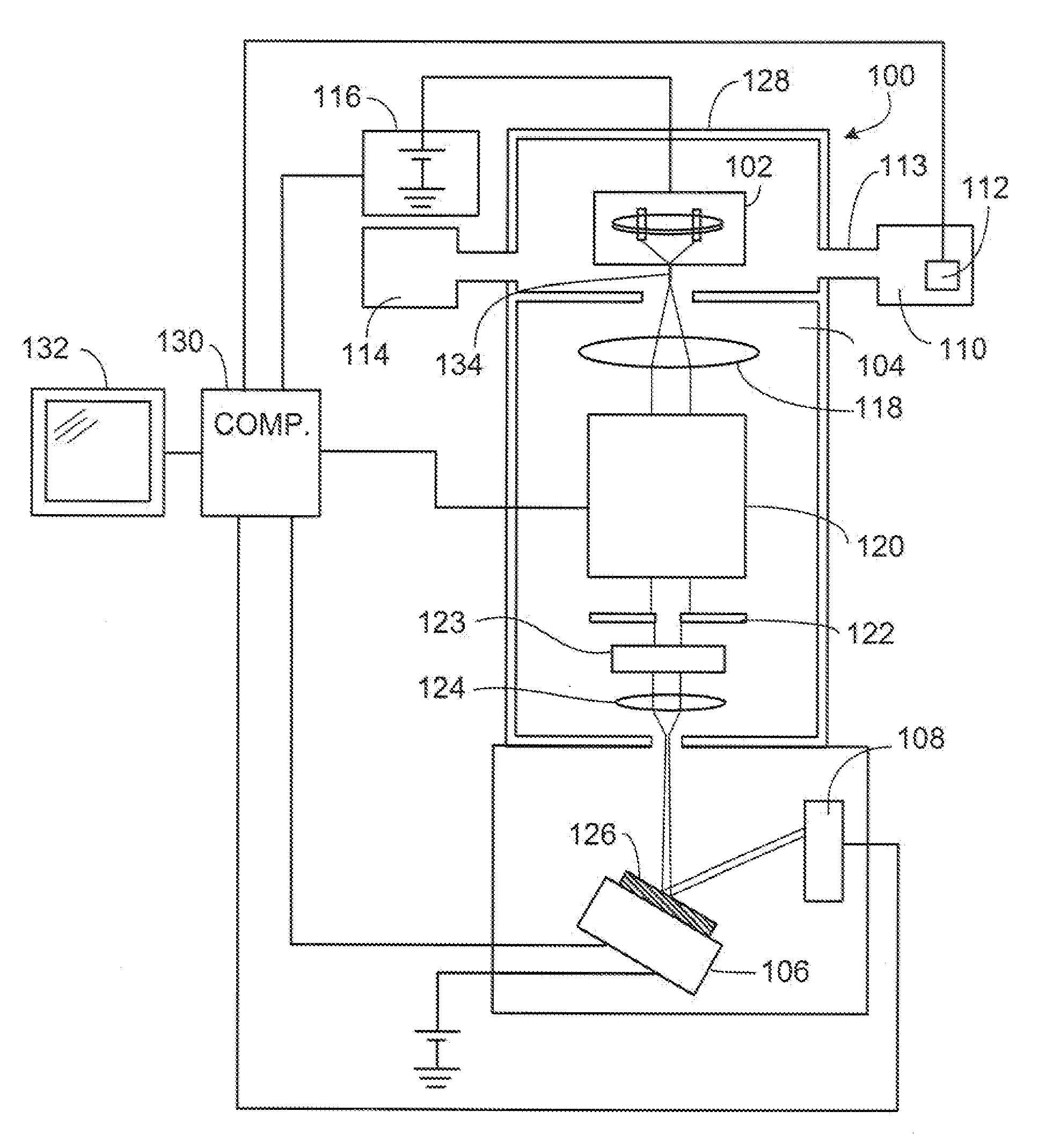
[0024]As will be seen from the following description, in one aspect the invention provides a gas field ion microscope that includes an ion source in connection with an optical column, such that an ion beam generated at the ion source travels through the optical column and impinges on a sample. The ion source includes an emitter having a width that tapers to a tip comprising a few atoms. In other aspects, the invention provides methods for using the ion microscope to analyze samples and enha...


PUM


Abstract

In one aspect the invention provides a gas field ion microscope that includes an ion source in connection with an optical column, such that an ion beam generated at the ion source travels through the optical column and impinges on a sample. The ion source includes an emitter having a width that tapers to a tip comprising a few atoms. In other aspects, the invention provides methods for using the ion microscope to analyze samples and enhancing the performance of a gas field ion source.

Description


Claims


Application Information

Patent Timeline
Owner ALIS CORP
Why Eureka
Try Eureka