Brake controller and method for controlling brakes

Inactive Publication Date: 2007-09-20
TOYOTA JIDOSHA KK
View PDF8 Cites 26 Cited by
  • Summary
  • Abstract
  • Description
  • Claims
  • Application Information

AI Technical Summary

Benefits of technology

[0007]Given the foregoing, the present invention provides a bra

Problems solved by technology

Thus, when the index has poor accuracy due to, for example, an external disturbance, the inacc

Method used


Image

  • Brake controller and method for controlling brakes
  • Brake controller and method for controlling brakes
  • Brake controller and method for controlling brakes

Examples


Embodiment Construction

[0028]An embodiment of the present invention is described in detail below, with references made to the drawings.

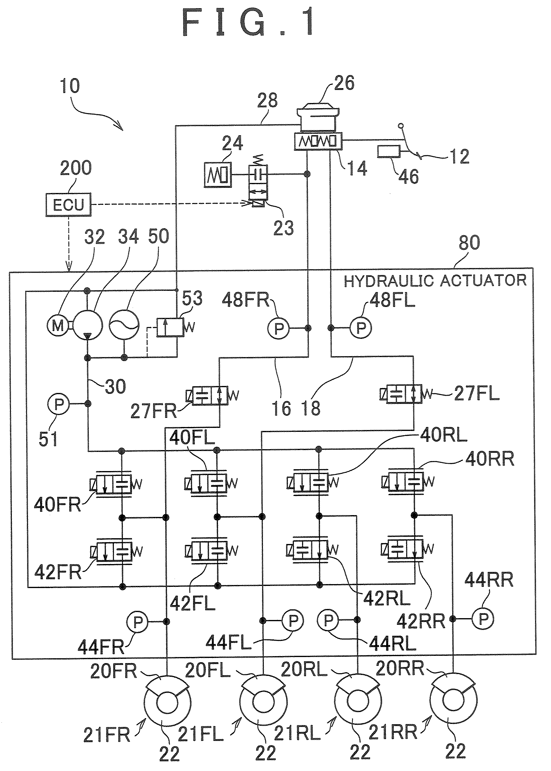
[0029]FIG. 1 is a schematic view of a brake controller 10 according to an embodiment of the present invention. The brake controller 10 shown in FIG. 1 is an electronically controlled brake system for a vehicle, in which the brakes of the four wheels of the vehicle are independently and optimally set in response to the operation of a brake operating member, such as a brake pedal 12. The vehicle into which the brake controller 10 of this embodiment is installed has a steering device (not illustrated) that steers the steered wheels of the four wheels, and a drive source (not illustrated) such as an internal combustion engine or motor or the like that drives the driving wheels of the four wheels of the vehicle.

[0030]The disc brake units 21FR, 21FL, 21RR, 21RL, which are the braking force application mechanisms, apply braking force to the front-right wheel, the front-left wheel...


PUM


Abstract

A brake controller is provided, having a braking force application mechanism that presses a friction member against a braked member so as to apply a braking force to a wheel of a vehicle; and a control unit that calculates an index indicating the difference between an estimated braking effectiveness and an actual braking effectiveness, and calculates a correction amount using the index, determines that the index is inaccurate. The control unit further limits the change in the correction amount calculated using the index, if it is determined that the index is inaccurate, and corrects a target value, which is set to control a pressing force of the friction member, based on the correction amount to reduce a variation in a braking effectiveness of the vehicle.

Description

INCORPORATION BY REFERENCE[0001]The disclosure of Japanese Patent Application No. 2006-71069 filed on Mar. 15, 2006 including the specification, drawings and abstract is incorporated herein by reference in its entirety.BACKGROUND OF THE INVENTION[0002]1. Field of the Invention[0003]The present invention relates to a brake controller and method of controlling the braking force applied to the wheel of a vehicle.[0004]2. Description of the Related Art[0005]A conventional electronically controlled brake control system for a vehicle (for example, in Japanese Patent Application Publication No. 62-18359 (1987)) generates a deceleration error signal by comparing the driver braking request signal with the measured deceleration. This brake system further has a means for correcting the braking request signal that generates an adaptive coefficient from the deceleration error signal and corrects the braking request signal by using an adaptive coefficient under prescribed conditions, such as vehi...

Claims


Application Information

Patent Timeline
IPC IPC(8): B60T8/60
CPCB60T17/22B60T8/172
Inventor MIYAZAKI, TETSUYAIRIE, YOSHIAKISUDA, RIO
Owner TOYOTA JIDOSHA KK
Why Eureka
Try Eureka