Rimless Spectacles And Hinge Pieces For Rimless Spectacles

a technology of rimless spectacles and hinge pieces, which is applied in the direction of optics, lens assemblies, non-optical parts, etc., can solve the problems of reducing the ability of the lens to withstand external forces on the hinge piece, reducing the ability of the lens to withstand external forces, and reducing the limit of the lens material

Inactive Publication Date: 2007-09-20
EVA TYBRING +2
View PDF6 Cites 8 Cited by
  • Summary
  • Abstract
  • Description
  • Claims
  • Application Information

AI Technical Summary

Benefits of technology

[0010] The rimless spectacles according to the present invention provides a solution to this, in that the hinge pieces each comprises an abutment part having an abutment surface extending parallel to and in abutment with a side surface of the respective lens and at least two corresponding pins, that are fastened to the abutment part and extend into corresponding h

Problems solved by technology

This compression force is in itself not harmful to the lens, but in case the hinge piece is subjected to an excessive extra force, e.g. in case the spectacles are accidentally dropped on the floor, the rupture limit of the lens material is more readily reached, resulting in damages of the lens.
Also in this case, the tension in the lens caused by the compression force from the fastening means lower the ability of the lens to withstand external forces on the hinge piece.
This allows for relative movements between the holding part and the hole in the lens, resulting over time in wear on the two parts, whereby the connection will become too loose to fulfil its function.
Furthermore, the oblong hole will only be partly filled by the holding part and the open or unfilled part of the hole constitutes a weakening of the strength of the lens as the restraint on the deformation of the lens material is diminished.
An impact of a force on the outer edge of the lens near the hole can easily cause a fracture of the lens due to the unfilled part of the hole allow

Method used


Image

  • Rimless Spectacles And Hinge Pieces For Rimless Spectacles
  • Rimless Spectacles And Hinge Pieces For Rimless Spectacles
  • Rimless Spectacles And Hinge Pieces For Rimless Spectacles

Examples


first embodiment

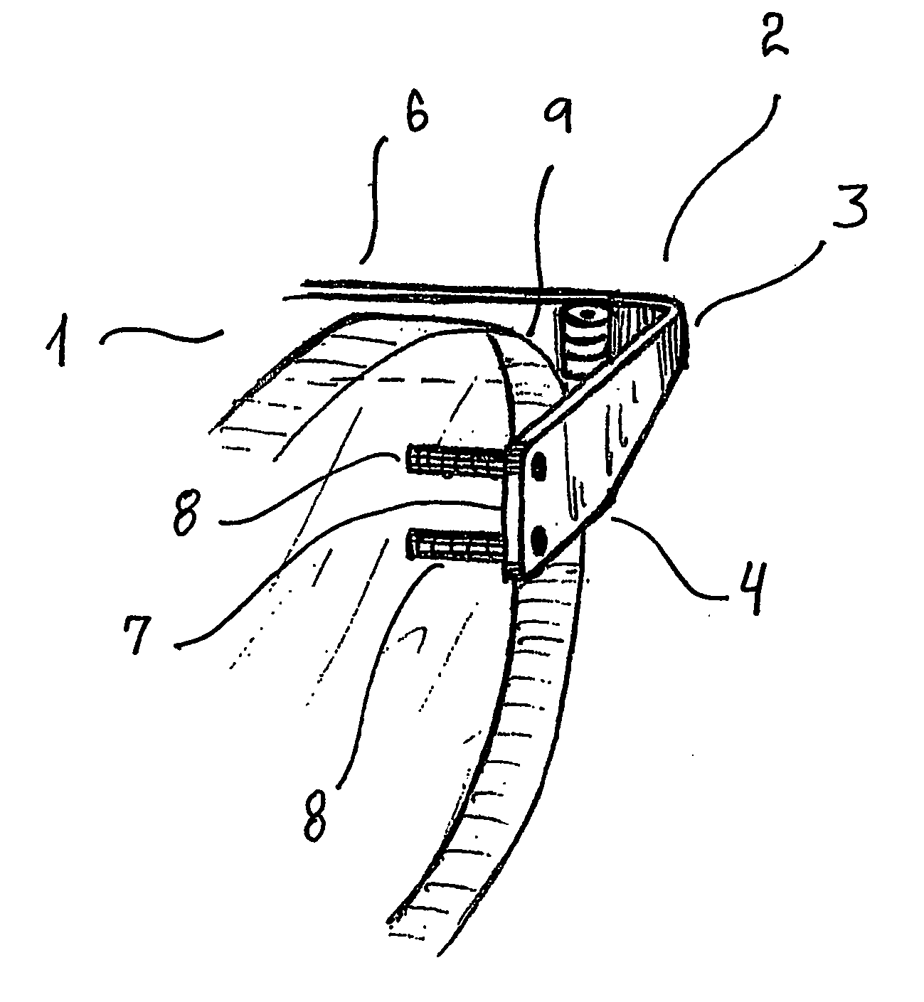
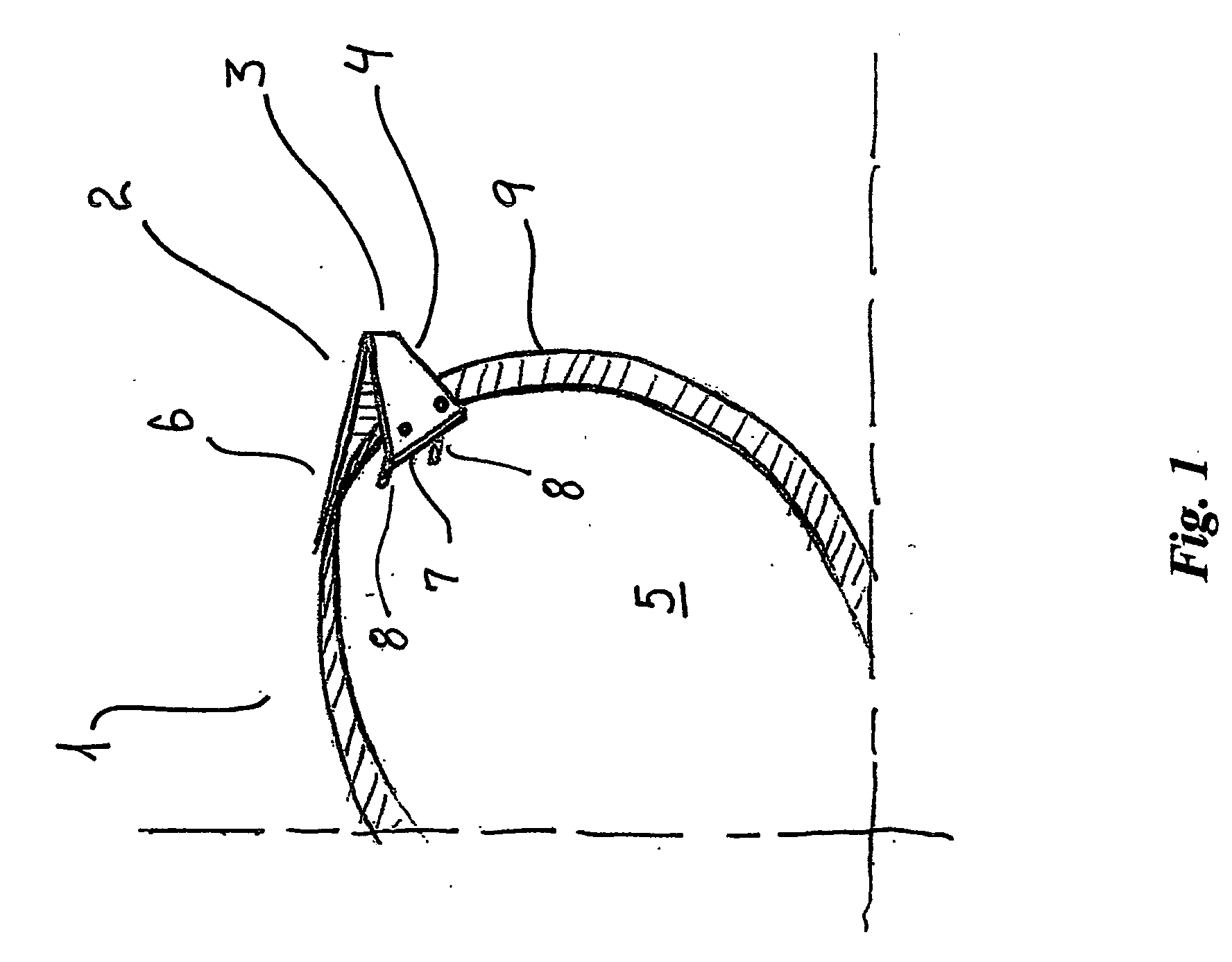
[0068] a lens 1 with a hinge piece 2 of spectacles according to the present invention is shown in FIG. 1, in which the hinge piece 2 is made from a laser cut or punched out piece of sheet metal that provided with a substantially right angled bent 3 so that an abutment part 4 of the hinge piece 2 is parallel with the front side surface 5 of the lens 1 and a hinge carrying part 6 extending towards the back of a user for connecting with a temple of the spectacles. The inner side surface 7 of the abutment part is in abutment with a part of the front side surface 5 of the lens 1, and two pins 8 are fastened, e.g. soldered, glued or welded to the abutment part 4 so that they extend from the abutment surface 7 of the abutment part 4. The pins 8 are in an interference fit with the two corresponding holding holes though the lens 1, so that the abutment part 4 and the two pins 8 form an unbroken three-sided contact between the hinge piece 2 the lens 1. The distance between the two pins 8 is f...

second embodiment

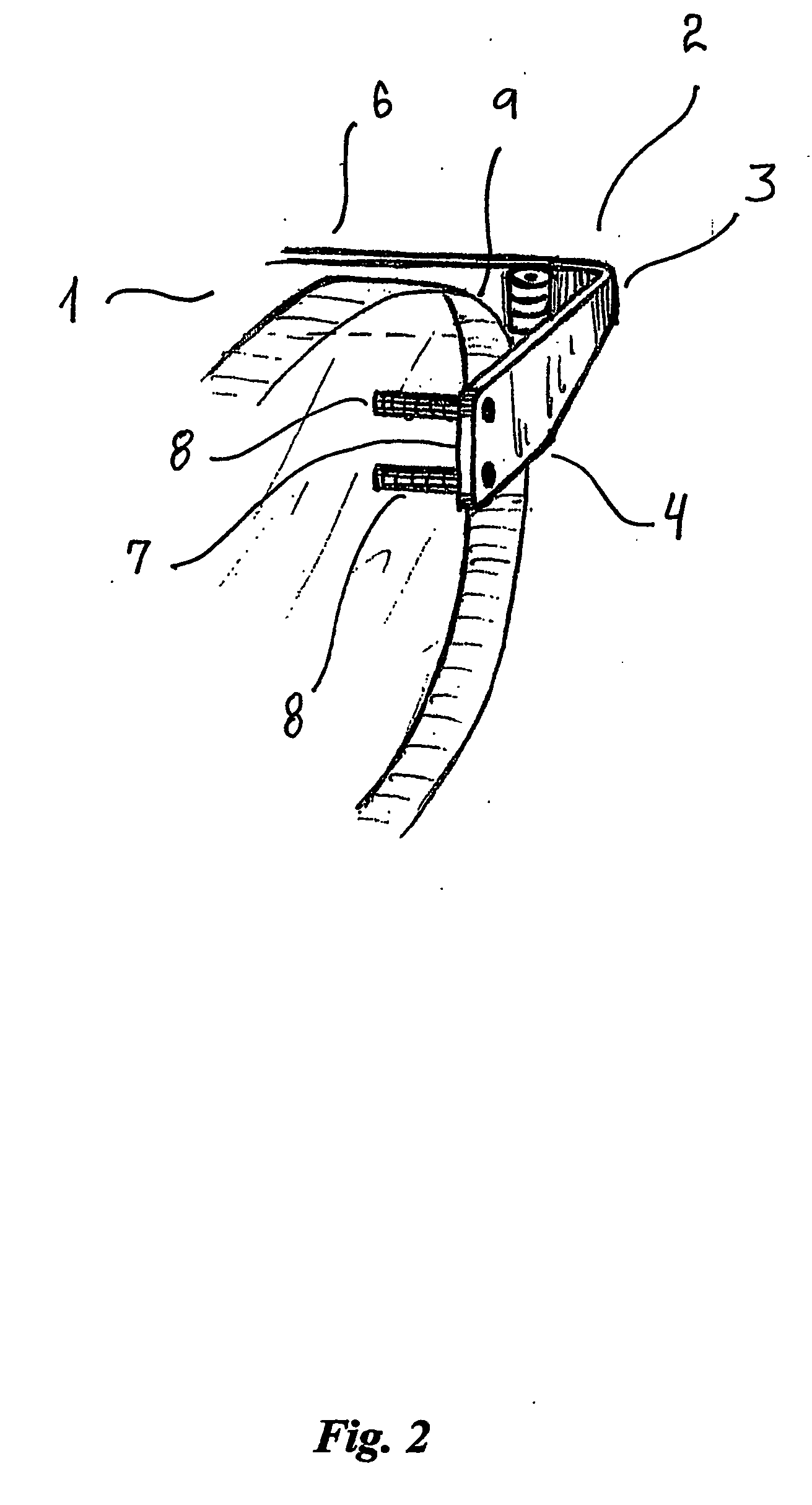
[0069] a lens 1 with a sheet metal hinge piece 2 of spectacles according to the present invention is shown in FIG. 2. The deviation from the embodiment of FIG. 1 is that the pins 8 are arranged vertically on line.

third embodiment

[0070] a lens 1 with a sheet metal hinge piece 2 of spectacles according to the present invention is shown in FIGS. 3A and 3B. This embodiment deviates from the two shown in FIGS. 1 and 2 in that the pins 8 and the corresponding holding holes 10, 11 are arranged substantially horizontally on line, which in general has been found to be an advantage for spectacles according to the present invention, because the distance from the innermost holding hole 11 to the outer side edge 9 of the lens 1 is maximised and the weakening of the ability of the lens 1 to withstand mechanical stresses is consequently minimised.

[0071] The fourth embodiment shown in FIGS. 4A, 4B and 4C of a lens 1 with a sheet metal hinge piece 2 of spectacles according to the present invention deviates from the third embodiment of FIGS. 3A and 3B in that the lens 1 is provided with an indentation 12 in the front side surface 5 and the surface of the indentation 12 is in abutment with the abutment surface 7 of the hinge ...


PUM


Abstract

Rimless spectacles and hinge pieces are disclosed, where the hinge pieces each include an abutment part having an abutment surface extending parallel to and in substantial abutment with a side surface of the respective lens and at least two corresponding pins, that are fastened to the abutment part and extend into corresponding holding holes of the lenses. The pins are rigidly connected to the inner side surfaces of the corresponding holes, so that the pins substantially are prevented from gaining an angular displacement relatively to the holes in the lens. The two pins form together with the abutment part a three-sided contact area between the hinge piece and the lens. A force or torque applied to the hinge piece is distributed over this contact area, since the construction substantially prevents any mutual movements or displacements between the hinge piece and the lens, and the stresses are consequently distributed and fatal stress concentrations leading to damages and fractures of the lens are avoided.

Description

[0001] The present invention relates to rimless spectacles in which the hinge pieces are fastened to the respective lenses in a way to reduce stress concentrations in the lenses. The invention also relates to spectacle hinge pieces suitable for this purpose. BACKGROUND [0002] Rimless spectacles have been known for many years, in which the bridge piece interconnecting the lenses and supporting on the nose of the user, as well as the hinge pieces connecting the outer side edges of the lenses with the temples or side bars, are fastened directly to the lenses so that the lenses constitute a construction part of the spectacles instead of being fitted into the rims of a spectacle frame. [0003] A very commonly used means for fastening the hinge piece to the lens is by screw and nut, i.e. by providing screws with a threaded tip through one or more holes in the lens and fastening the screws in place with corresponding female parts on the other side of the lens as disclosed e.g. in U.S. Pat. ...

Claims


Application Information

Patent Timeline
IPC IPC(8): G02C1/02
CPCG02C1/02
Inventor GROVE, ANDERS
Owner EVA TYBRING
Why Eureka
Try Eureka