Projection apparatus, projection method, and computer program

a projection device and projection method technology, applied in the field of projection devices, can solve the problems of requiring a lot of care and manufacturing, difficult to perform such precise control, and unused light (useless light) that is not projected on the screen

Active Publication Date: 2007-09-20
CASIO COMPUTER CO LTD
View PDF18 Cites 44 Cited by
  • Summary
  • Abstract
  • Description
  • Claims
  • Application Information

AI Technical Summary

Benefits of technology

[0009]A projection apparatus according to the present invention comprises: a color wheel including a transmission region which allows at a red ray of light emitted from a light source to pass therethrough, a transmission region which allows a blue ray of the light to pass therethrough, and a transmission region which allows a green ray of the light to pass therethrough; a sensor which detects a ray of light that has passed through the color wheel and has been modulated by a light modulation device; and a

Problems solved by technology

In other words, when a black image is projected, there exists unused light (useless light) that is not projected on the screen.
However, since color wheels need individual adjustments

Method used


Image

  • Projection apparatus, projection method, and computer program
  • Projection apparatus, projection method, and computer program
  • Projection apparatus, projection method, and computer program

Examples


Embodiment Construction

[0038]A projection apparatus 1 according to an embodiment of the present invention will be explained below.

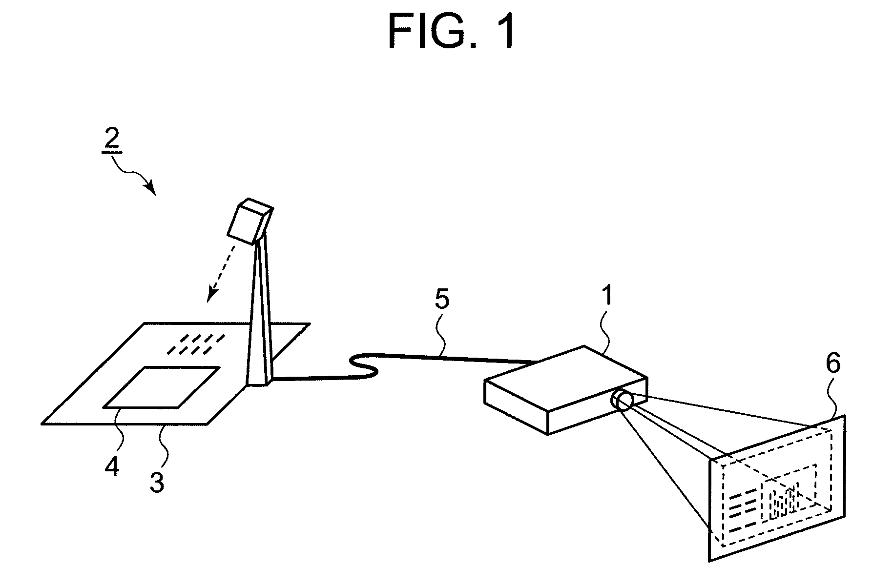
[0039]FIG. 1 is a diagram showing an example of an image projection system using the projection apparatus 1.

[0040]A camera 2 captures an image of a script sheet 4 placed on a base 3. The obtained captured image is input to the projection apparatus 1. The projection apparatus 1 and the camera 2 are connected by a cable 5. The projection apparatus 1 converts the captured image input from the camera 2 into a projection light. The projection apparatus 1 irradiates this projection light and projects an image including the script sheet 4 onto a screen 6.

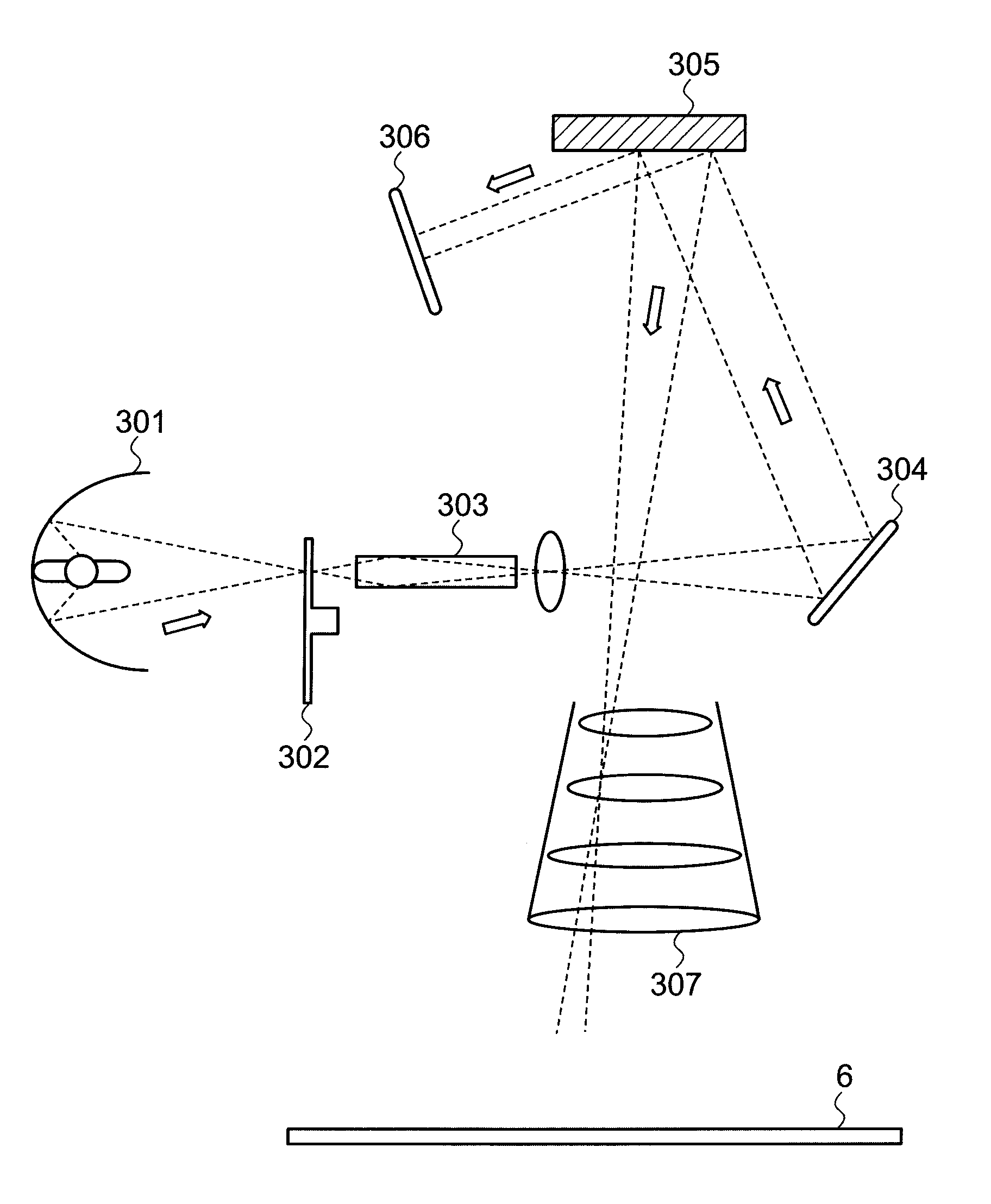
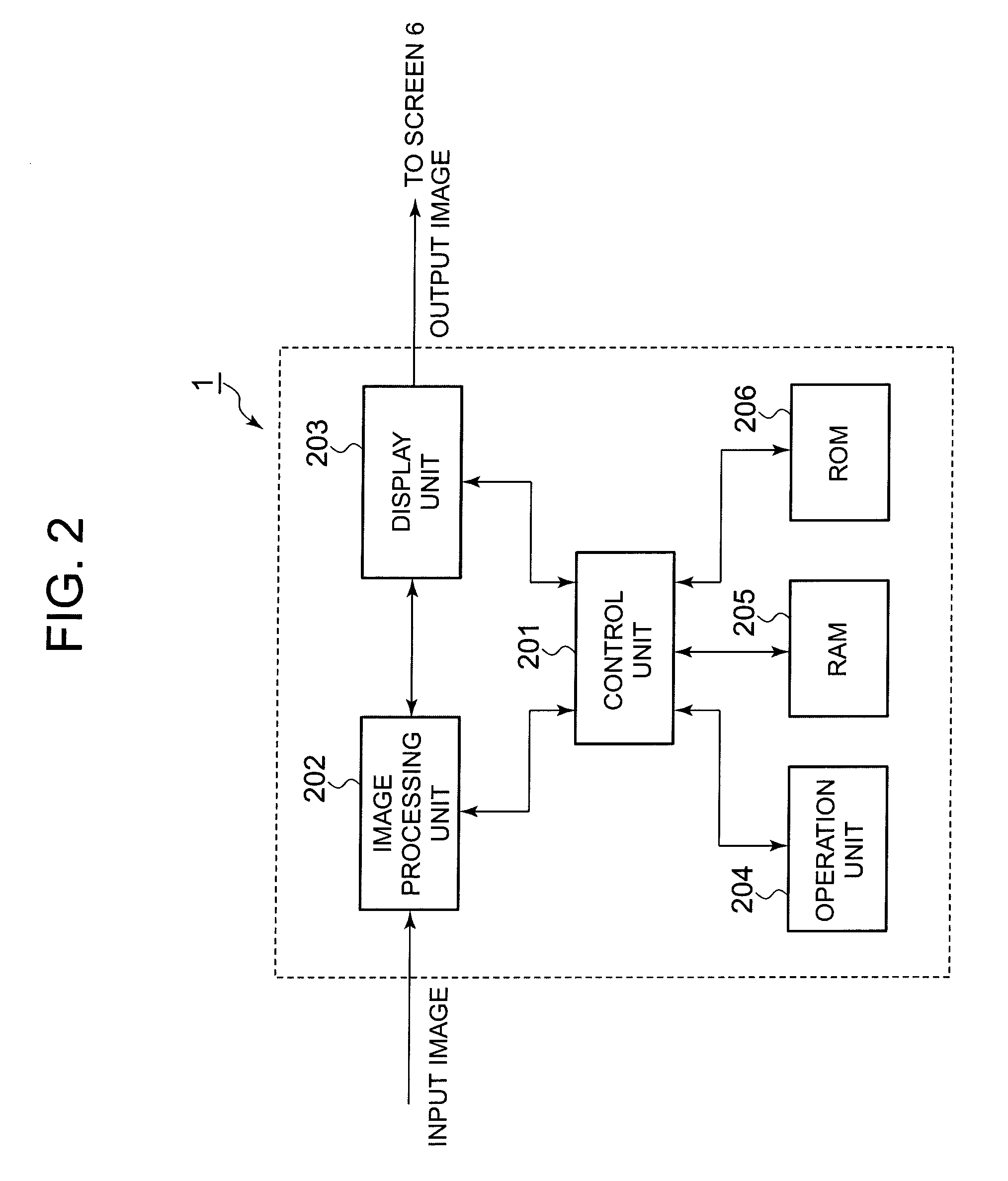
[0041]Next, the structure of the projection apparatus 1 according to the present embodiment will be explained with reference to FIG. 2. The projection apparatus 1 comprises a control unit 201, an image processing unit 202, a display unit 203, an operation unit 204, a RAM(Random Access Memory) 205, and a ROM (Read Only Memory) 206.

[004...


PUM


Abstract

Light emitted from a lamp enters a color wheel having a region for allowing a predetermined color to pass therethrough, is reflected on a mirror, and enters a DMD. After this, the light is reflected by the DMD and enters a color sensor, which then detects the color of the transmitting light. A projection apparatus automatically synchronizes the control on the rotation of the color wheel and the control on the proceeding direction of the transmitting light by the DMD, based on a color time-division pattern of the transmitting light detected by the color sensor.

Description

BACKGROUND OF THE INVENTION[0001]1. Field of the Invention[0002]The present invention relates to a projection apparatus, a projection method, and a computer program for controlling the projection apparatus.[0003]2. Description of the Related Art[0004]Projection apparatuses generally called projector have become popular as apparatuses for projecting images on a screen. For example, some projectors adopt a single-plate DMD (Digital Micromirror Device™), as one projection method. Such a projector comprises a minute mirror (DMD) whose angle can be controlled. By focusing light, which passes through a rapidly rotating color wheel (color filter) on which red (R), green (G), and blue (B) are arranged, on the DMD, this projector can continuously display images corresponding to these colors respectively. In projecting a black image, the projector uses the DMD to reflect light toward a light absorption plate, and reduces the amount of projection light to be directed to the screen. In other wo...

Claims


Application Information

Patent Timeline
IPC IPC(8): G03B21/14
CPCH04N9/3114H04N9/3197H04N9/3182H04N9/31H04N5/74G03B21/00
Inventor NARIKAWA, TETSURO
Owner CASIO COMPUTER CO LTD
Why Eureka
Try Eureka