Color wheel device and projector using the same

a color wheel and projector technology, applied in the field of projectors, can solve the problems of color contrast decrease, short brightness, and conventional projectors

Inactive Publication Date: 2007-04-19
PLUS VISION CORP
View PDF5 Cites 34 Cited by
  • Summary
  • Abstract
  • Description
  • Claims
  • Application Information

AI Technical Summary

Benefits of technology

[0009] One purpose of the present invention resolves the above problems and provides the color wheel device that

Problems solved by technology

Furthermore, if all regions of the color wheel are formed of three primitive color filters, the brightness may be short.
However, the additional region for partially transmitting the white light of the color wheel makes the color contrast decrease.
However, conventional projectors have the following problems.
For example, Laid-open 09-163391, Laid-open 2003-307705 and patent application No. 2003-90290 need the switching apparatus for moving the color wheel, wh

Method used


Image

  • Color wheel device and projector using the same
  • Color wheel device and projector using the same
  • Color wheel device and projector using the same

Examples


Embodiment Construction

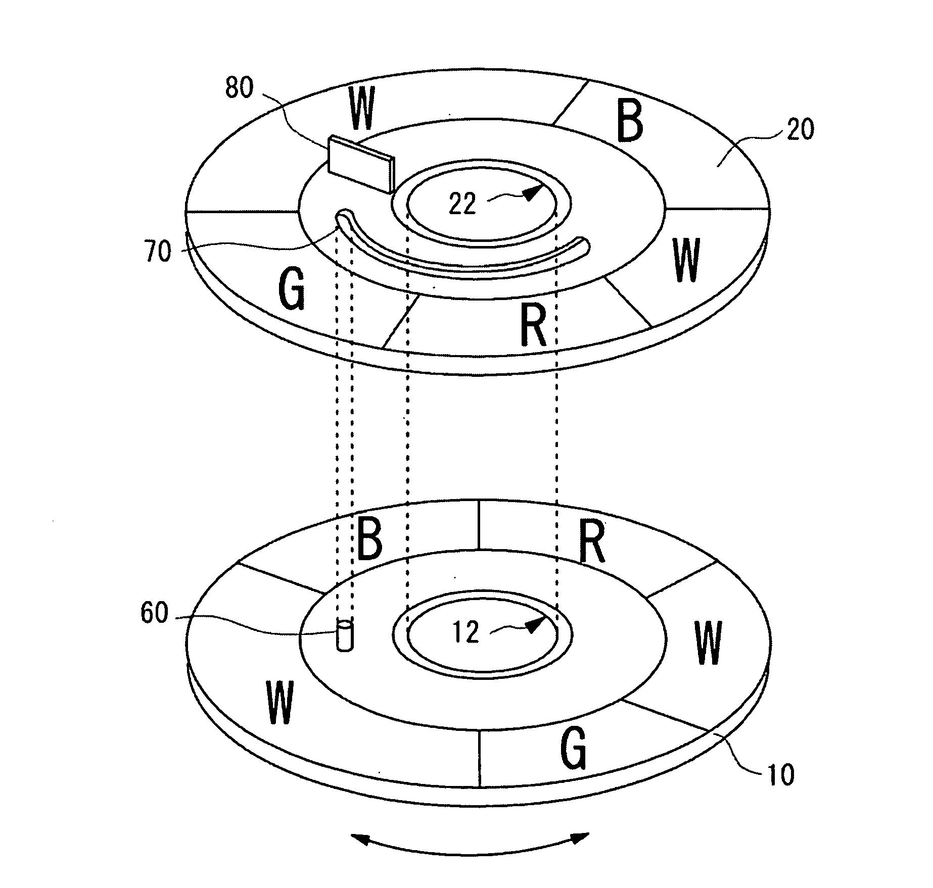
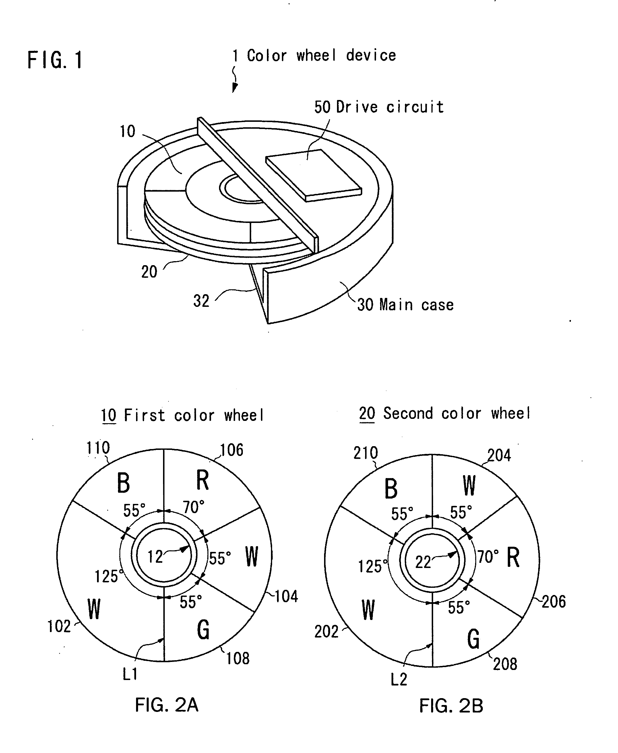
[0055]FIG. 1 shows an overview of a color wheel device according to an embodiment of the present invention. As shown in FIG. 1, the color wheel device 1 includes a first color wheel 10, a second color wheel 20 fitted on the same rotation axis as the first color wheel 10, a main case 30 accommodating the first and second color wheels, a motor 40 (see FIG. 5) coupled with a bearing of the first and second color wheels, and selecting means for selecting the relative location between the first and second color wheels. A cut-away portion 32 is formed in the main case 30. A white light from a light source enters into the first color wheel 10 through the cut-away portion 32 and is outputted from the second color wheel 20.

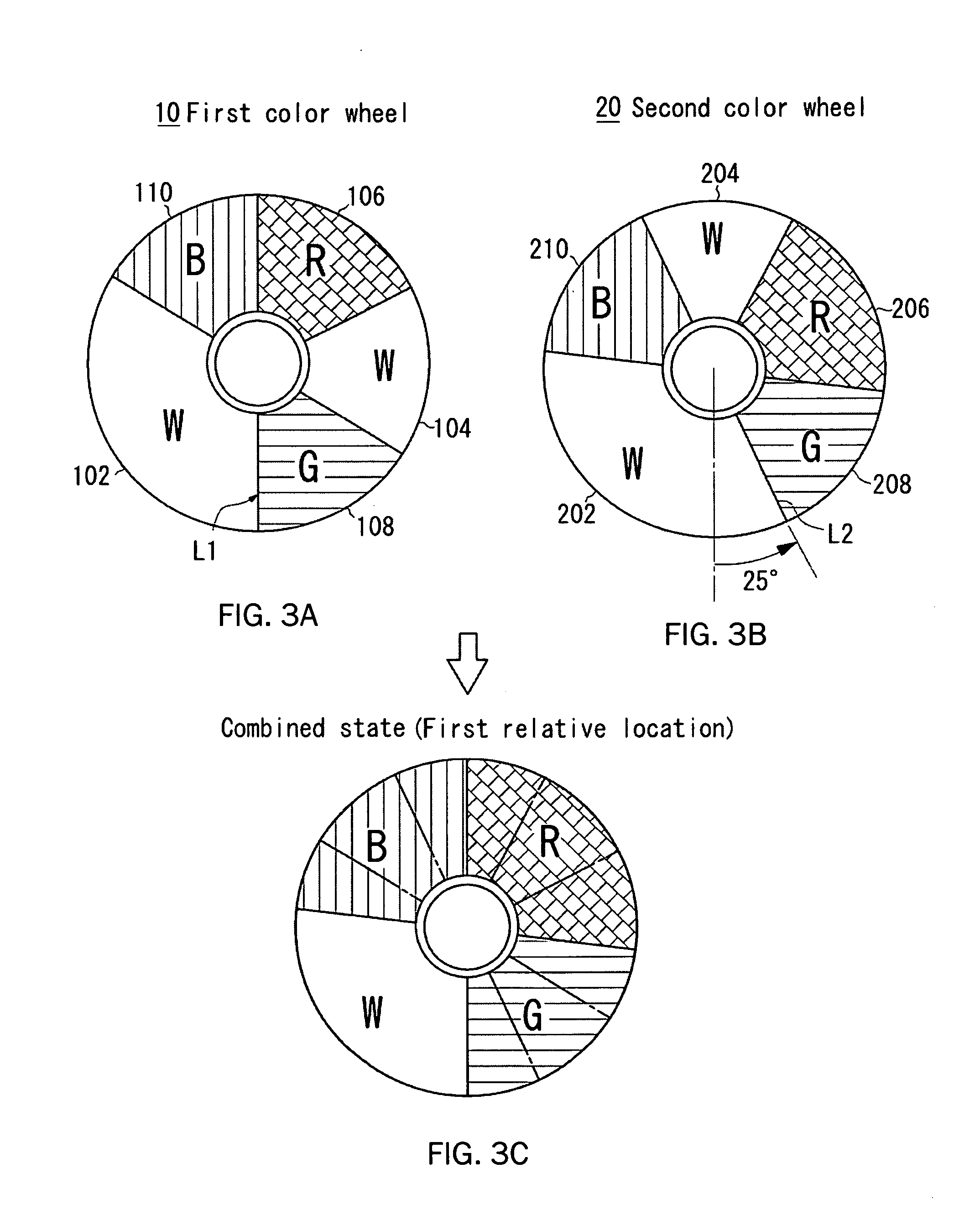
[0056]FIGS. 2a and 2b show a plan view of the first and second color wheels. The first color wheel 10 is made of glass material of a circular thin plate. A circular through-hole 12 is formed at a central portion of the first color wheel 10. The through-hole 12 turns to a ...


PUM


Abstract

A color wheel device can set a desired display mode without using a complex mechanical apparatus. For example, a color wheel device 1 includes a first color wheel 10 having transmitting regions of W, R, G, B in a circumferential direction and rotated on an axis, a second color wheel 20 having transmitting regions of W, R, G, B in a circumferential direction and rotated at the same axis of the first color wheel, and selecting means for selecting a relative location between the first and second color wheels 10, 20. While the first and second color wheels are rotated, the light is entered into the first color wheel 10 and is outputted from the second color wheel 20.

Description

[0001] This application is a continuation of co-pending International Application No. PCT / JP2004 / 018789, filed Dec. 16, 2004, which designated the United States and was not published in English, and which is based on Japanese Application No. 2004-117505 filed Apr. 13, 2004, both of which applications are incorporated herein by reference.TECHNICAL FIELD [0002] The present invention relates to a projector using a space-modulation device, and more particularly, to a DLP™ type projector using a DMD (Digital Micro-mirror Device). BACKGROUND [0003] Projectors for displaying color images using the DMD or a liquid crystal device as the space-modulation device have come into a practical use. The DLP™ type projector using the DMD displays the color images by scaling up the reflected light from the DMD with optics such as a lens, etc. The DMD is made of a semiconductor device and reflects a light. [0004] Applicant discloses the DLP™ type projector in Japanese Patent No. 3,121,843 and correspon...

Claims


Application Information

Patent Timeline
IPC IPC(8): G02B7/00G02B5/20G02B26/00G03B21/14H04N9/31
CPCG02B7/006G02B26/008G03B21/14H04N9/3114H04N9/3197G03B33/08
Inventor SEKIGUCHI, NOBUTOSHIOMI, SATOSHIISHII, AKIO
Owner PLUS VISION CORP
Why Eureka
Try Eureka