Projection optical system improving light utilization rate and projection brightness

A technology of projection optical system and utilization rate, which is applied in the field of projection optical system, can solve problems such as low light utilization rate and complex system structure, and achieve the effect of simplifying the cooling system, reducing the complexity of the system, and reducing heat

Active Publication Date: 2016-05-11
BEIJING GUOWANG OPTICAL TECH CO LTD
View PDF7 Cites 33 Cited by
  • Summary
  • Abstract
  • Description
  • Claims
  • Application Information

AI Technical Summary

Problems solved by technology

[0003] The purpose of the present invention is to propose a projection optical system that improves light utilization rate and...

Method used


Image

  • Projection optical system improving light utilization rate and projection brightness

Examples


Embodiment Construction

[0018] Embodiments of the present invention will be further described below in conjunction with the accompanying drawings.

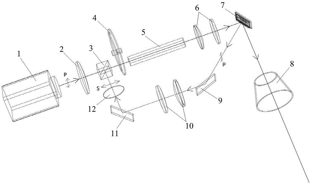
[0019] See attached figure 1 , the projection optical system of the present invention improves light utilization rate and projection brightness and comprises laser light source 1, converging mirror 2, polarized beam splitting prism 3, color wheel 4, integral square rod 5, relay mirror group A6, DMD7, projection lens 8 and folding mirror group;

[0020] The polarized light P emitted by the laser light source 1 is converged by the converging mirror 2 and then transmitted through the polarization beam splitter prism. The polarized light P transmitted through the polarization beam splitter prism 3 is incident on the DMD7 through the color wheel 4, the integrating square rod 5 and the relay mirror group A6 in sequence. , the outgoing light in the projection direction of the DMD7 exits through the projection lens 8, and the outgoing light in the non-projectio...


PUM


Abstract

The invention belongs to the field of design projection equipment optical systems, particularly relates to a projection optical system improving a light utilization rate and projection brightness, andaims to solve the problem of low light utilization rate and complex system structure which exist in the prior art. Polarized light P emitted by a laser source passes through a convergent mirror and is transmitted by a polarized beam splitter prism, polarized light P transmitted by the polarized beam splitter prism passes through a color wheel, an integral square rod and a relay lens group in sequence and is incident to a DMD, emergent light in a projection direction of the DMD is emergent through a project lens, emergent light in a non-projection direction of the DMD passes through a reflex lens group to obtain polarized light S, and polarized light S reflected by the polarized beam splitter prism and the polarized light P transmitted by the polarized beam splitter prism are coaxially incident to the color wheel; and the reflex lens group includes a total reflector A, a relay lens group B, a total reflector B and a 1/2 wave plate; and the emergent light in the non-projection directionof the DMD is sequentially reflected by the total reflector A and refracted by the relay lens group B and 1/2 wave plate to obtain polarized light S.

Description

technical field [0001] The invention belongs to the field of optical system design of projection equipment, and in particular relates to a projection optical system for improving light utilization rate and projection brightness. Background technique [0002] The single-chip DMD projection equipment is small in size and simple in optical-mechanical structure, and is widely used in the market. However, due to the limitation of the projection principle of the DMD, with the different projection screens, there will be an indeterminate amount of light exiting through the non-projection direction of the DMD, resulting in The waste of light sources reduces the light utilization rate and projection brightness of single-chip DMD projection equipment. At the same time, due to the heat dissipation problem that the outgoing light in the non-projection direction is converted into heat, it is necessary to design a high-performance heat dissipation system, which increases to a certain extent...

Claims


Application Information

Patent Timeline
IPC IPC(8): G03B21/20G03B21/00
CPCG03B21/008G03B21/2033G03B21/2066G03B21/2073
Inventor 王飞芮大为田伟张巍
Owner BEIJING GUOWANG OPTICAL TECH CO LTD
Why Eureka
Try Eureka