Constant-weight bit-slice PWM method and system for scrolling color display systems

a color display system and constant-weight bit-slice technology, applied in the field of color displays, can solve the problems of significant light loss, scattered light loss,

Active Publication Date: 2006-06-13
TEXAS INSTR INC
View PDF27 Cites 36 Cited by
  • Summary
  • Abstract
  • Description
  • Claims
  • Application Information

AI Technical Summary

Benefits of technology

[0016]In another embodiment, a digital display system includes a digital video source. A sequencer receives control signals from the video source and a data arranger (e.g., multiplexer) receives data signals from the video source. A graphics memory receives arranged data signals from the data arranger. The arranged data signals form an array of pixels arranged in rows and columns. This array includes curved color bands during a first time period and rectangular color bands during a second time period. Once again, the second time period is concurrent with but of a shorter duration than the first time period. A digital micromirror device can receive control date from the sequencer and graphics data from the graphics memory.

Problems solved by technology

However, when a single color is applied to the DMD in a FSC system, the complement colors are being reflected by the color wheel and this light is scattered and lost.
This is a very significant light loss and a method is needed to recapture this lost lamp light.

Method used


Image

  • Constant-weight bit-slice PWM method and system for scrolling color display systems
  • Constant-weight bit-slice PWM method and system for scrolling color display systems
  • Constant-weight bit-slice PWM method and system for scrolling color display systems

Examples


Embodiment Construction

[0046]The making and using of the presently preferred embodiments are discussed in detail below. It should be appreciated, however, that the present invention provides many applicable inventive concepts that can be embodied in a wide variety of specific contexts. The specific embodiments discussed are merely illustrative of specific ways to make and use the invention, and do not limit the scope of the invention.

[0047]The present invention will be described with respect to preferred embodiments in a specific context, namely a DMD-based display system. The invention may also be applied, however, to other color display systems. For example, systems that utilize other spatial light modulators, such as liquid crystal displays or plasma displays, can also utilize concepts of this invention.

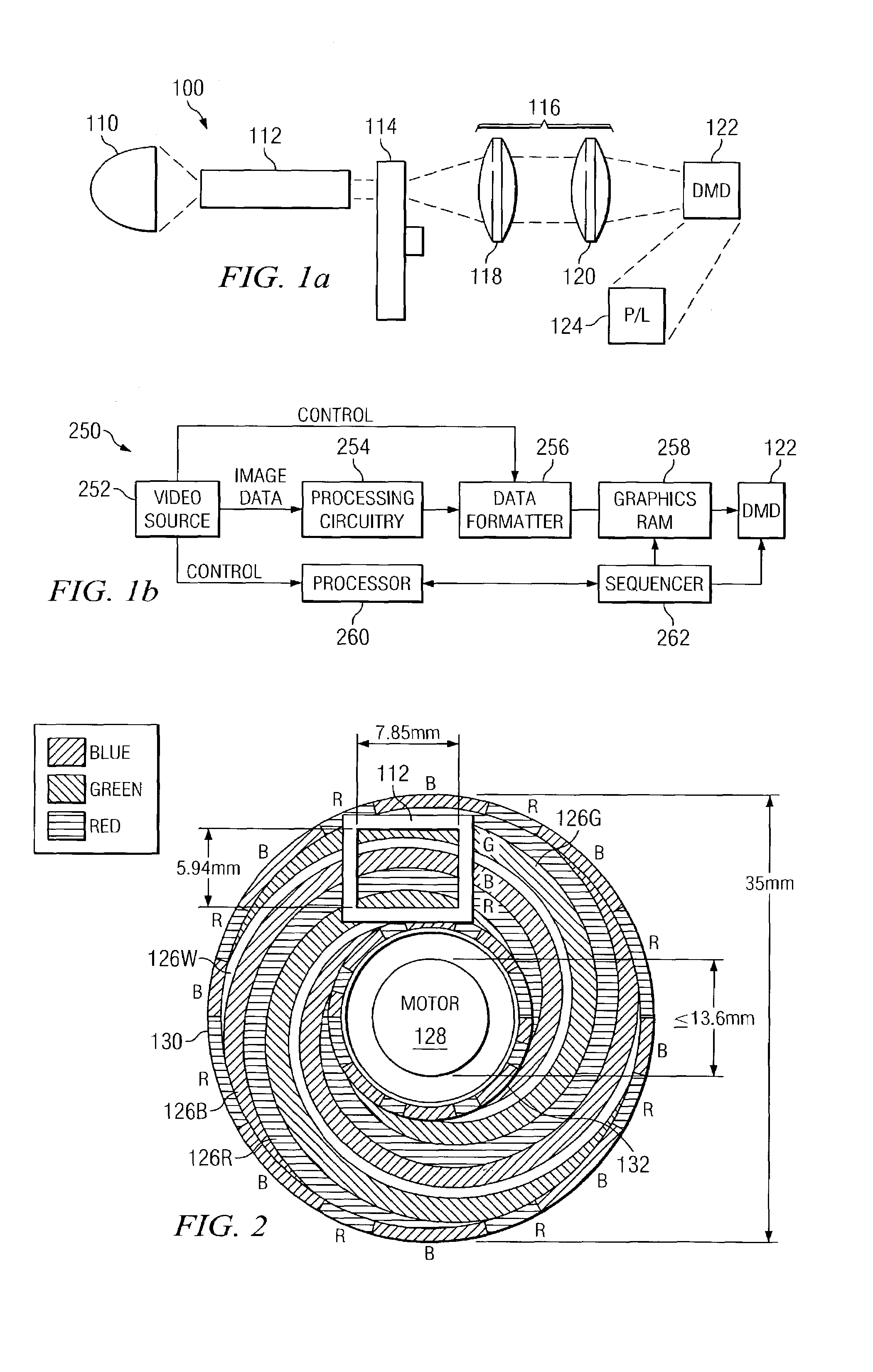
[0048]As discussed in the background, one goal of display design, especially designed based on color-wheels, is to recapture the maximum amount of light possible. SCR (sequential color recapture) is an ...


PUM


Abstract

A display system 100 includes a light source 110 and a color wheel 114. An optical section 112 is arranged to receive light from the light source 110 and to direct the light toward a color wheel 114. A digital micromirror device 122 is arranged to receive the light from the color wheel 114 and to direct image data toward a display. The image data includes an array of pixels arranged in rows and columns. The array of pixels is arranged as curved color bands during a first time period and rectangular color bands during a second time period. The second time period being concurrent with but of a shorter duration than the first time period.

Description

[0001]This application claims the benefit of U.S. Provisional Application No. 60 / 387,857, filed on Jun. 11, 2002, entitled “Control Electronics,” which application is hereby incorporated herein by reference.CROSS-REFERENCE TO RELATED APPLICATIONS[0002]This application relates to the following patents and co-pending, commonly-assigned patent applications. Each of these documents is incorporated herein by reference.[0003]U.S. Pat. or Ser. No.Filing DateIssue Date09 / 088,674Jun. 2, 1998—6,771,325Nov. 3, 2000Aug. 3, 20046,642,969Dec. 21, 2000Nov. 4, 200309 / 795,402Feb. 26, 2001—6,591,022Dec. 21, 2001Jul. 8, 2003[concurrently herewith]—10 / 458,045Jun. 10, 2003—5,061,049Sep. 13, 1990Oct. 29, 19915,192,946May 30, 1991Mar. 9, 19935,448,314Jan. 7, 1994Sep. 5, 19955,592,188Jan. 4, 1995Jan. 7, 19975,598,188Jun. 7, 1995Jan. 28, 19975,612,753Jan. 27, 1995Mar. 18, 19975,760,976Apr. 15, 1997Jun. 2, 19985,764,208Oct. 23, 1996Jun. 9, 19985,912,712May 11, 1998Jun. 15, 19995,969,710Aug. 30, 1996Oct. 19, ...

Claims


Application Information

Patent Timeline
Patent Type & Authority Patents(United States)
IPC IPC(8): G09G5/10G09G3/20G09G3/34G09G5/02H04N9/31
CPCH04N9/3117H04N9/3197G09G5/02G09G2310/0235G09G3/34G09G3/2014
Inventor MORGAN, DANIEL J.DOHERTY, DONALD B.SEXTON, WILLIAM J.
Owner TEXAS INSTR INC
Why Eureka
Try Eureka