Apparatus, a system and a method for collission avoidance

a technology of collision avoidance and apparatus, applied in the field of collision avoidance, can solve the problems of reducing productivity, damage to property (whether to vehicles or other structures), and death of the involved persons, and achieve the effect of avoiding collisions

Inactive Publication Date: 2011-10-13
BECKER MINING EURO GMBH
View PDF9 Cites 63 Cited by
  • Summary
  • Abstract
  • Description
  • Claims
  • Application Information

AI Technical Summary

Benefits of technology

[0018]The apparatus may find particular application in a mining environment, although its use is not necessarily limited thereto. The apparatus may find applications specifically in underground and / or surface mining. In fact, in one embodiment, an advantage of the apparatus is that it can transition between underground and surface mining operations with little or no disruption in functionality.
[0023]The UHF transceiver (or digital antenna) may be operable to receive and to generate and transmit UHF data packets of short burst duration. The control module may be configured to approximate a distance from the second apparatus based on a strength of a UHF signal received from the second apparatus. The communication range of the UHF transceiver may be up to 100 m. (1 m≈3.28 ft.) In fact, depending on the specific configuration of the UHF transceiver, the range may exceed 100 m. The control module may be capable of determining the distance of a second (proximate) apparatus with a resolution of approximately 15 m. Thus, UHF communication has the advantage of being long range, but has the disadvantage of having a low resolution (and hence a low accuracy).
[0026]The SHF transceiver (or radar antenna) may be operable to transmit and receive SHF data packets in rapid succession. The SHF signal typically has a range of between 5 m and 50 m. The “time of flight” of the SHF signal varies depending on the distance between transmitter and receiver, and by measuring minuscule differences in the time of flight of the signal, the SHF transceiver can provide resolution in the order of 0.5 m. Thus; using the SHF technology, good distance and excellent accuracy can be obtained. However, a drawback of this technology is that the SHF signal is easily compromised by adverse environmental operating conditions or obstructions.
[0037]The vehicle apparatus may include a plurality of VLF transceivers at locations around the vehicle to which the vehicle apparatus is mounted or installed. Each VLF transceiver may have a unique ID associated therewith. The VLF transceivers may be spaced at cardinal points around the vehicle which may be important for avoiding collisions with all portions of the vehicle, especially in larger vehicles. The vehicle apparatus may include an additional VLF transceiver within the cabin of the vehicle thereby to detect that an operator of the vehicle has about his person a personnel apparatus. Thus, the control module of the vehicle apparatus may be configured to disregard signals received from a personnel apparatus if it is determined that the personnel apparatus is within the cabin of the vehicle and not outside the vehicle. In this fashion, signal sent from the personnel device of the vehicle operator will not hamper the operation of the vehicle.

Problems solved by technology

These collisions can result in injury or death to the persons involved, damage to property (whether to vehicles or other structures), and at the very least, reduced productivity.
A foot cause of such collisions is poor visibility in mining environments.
These factors result in very poor visibility from the vehicle cabin.
In surface mining, the vehicles tend to be massive, in order to accommodate a larger payload, and therefore are quite cumbersome.
Again, visibility, with respect to objects on the ground (e.g. pedestrians or obstacles) tends to be poor.
However, these tags have a relatively low resolution and may be susceptible to interference.
In fact, general prior art systems do not provide satisfactory results due to oversimplification of the detection techniques and / or human notification interfaces.

Method used


Image

  • Apparatus, a system and a method for collission avoidance
  • Apparatus, a system and a method for collission avoidance
  • Apparatus, a system and a method for collission avoidance

Examples


Embodiment Construction

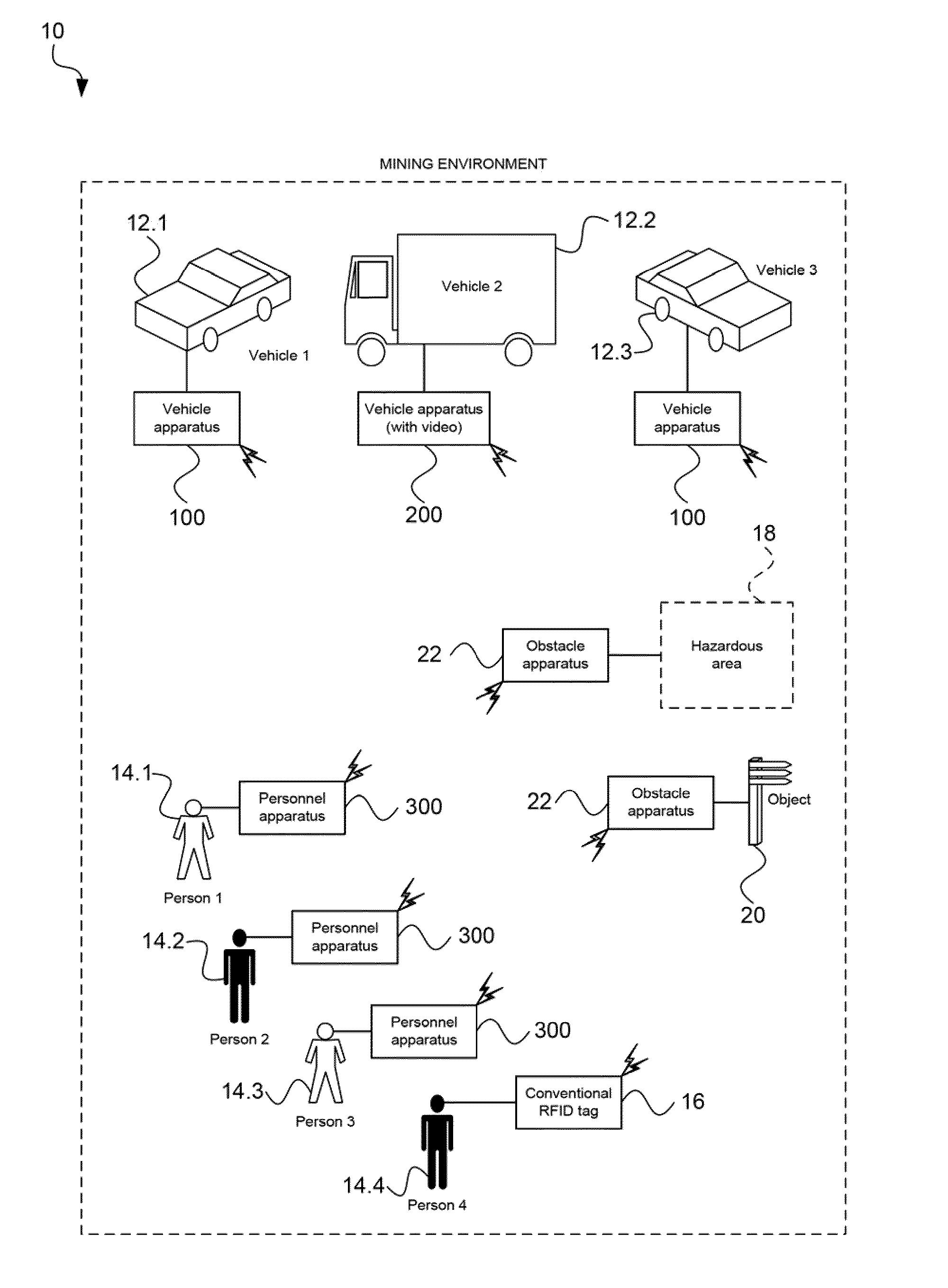
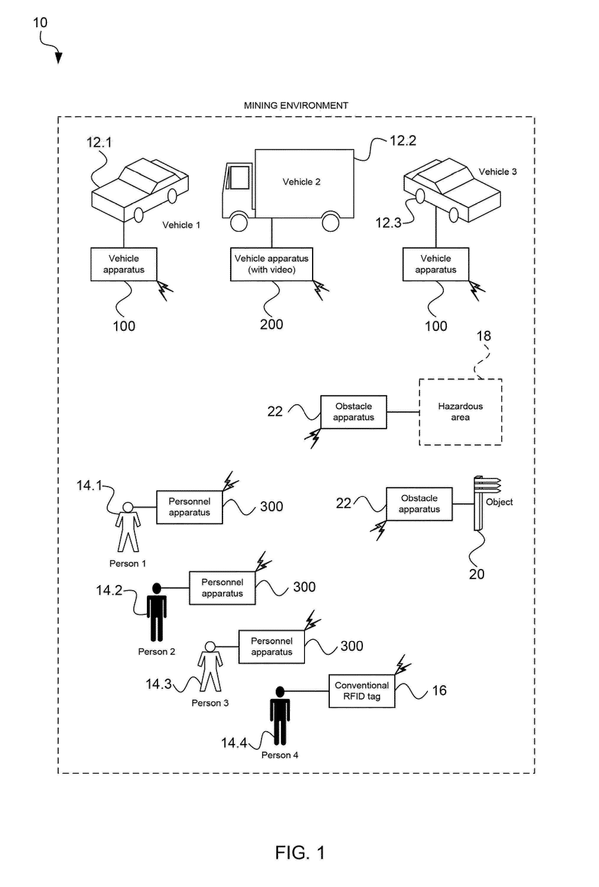
[0091]Referring initially to FIG. 1, reference numeral 10 generally indicates a system for collision avoidance, in accordance with the invention. Although this example embodiment is described with reference to a mining environment, it is to be appreciated that the apparatus, system and method in accordance with the invention may well be applicable to other environments or situations. The problem of collisions is particularly serious in mining environments due to the following factors: personnel (e.g. miners) and vehicles (e.g. trucks and mining machines) working in common areas, massive size of vehicles, reduced visibility, etc. Such collisions can lead to downtime, damage to equipment, injury, and in severe cases, loss of life.

[0092]Also, the mining environment can include aspects of both underground mining and surface mining. The system 10 is not only applicable to both, but can in fact transition from one to the other.

[0093]The system 10 includes a plurality of vehicles 12. Only ...


PUM


Abstract

The invention relate to a collision avoidance apparatus (100, 200, 300, 22), system (10) and method (500). The apparatus (100, 200, 300, 22) includes a UHF (Ultra High Frequency) transceiver (102) operable to send and receive UHF signals in electric field (E-field) mode, a VLF (Very Low frequency) transceiver (104) operable to send and receive VLF signals in magnetic field (H-field) mode, and a SHF (Super High Frequency) transceiver (106) operable to send and receive SHF signals in electric field (E-field) mode. The apparatus (100, 200, 300, 22) further includes a control module (110) operable to direct the operation of the respective transceivers (102, 104, 106), thereby to detect receipt of a signal via at least one of the transceivers (102, 104, 106), and determine whether or not an alert is to be issued, based on the nature of the received signal. The apparatus (102, 104, 106) also includes an output arrangement (112) operable to issue an alert in response to instruction from the control module (110) to do so.

Description

CROSS REFERENCE APPLICATIONS[0001]This application claims priority to U.S. Provisional Patent Application No. 61 / 323,368 filed 13 Apr. 2010, the contents of which is incorporated herein by reference.FIELD OF INVENTION[0002]This invention relates generally to collision avoidance, in relation to vehicles, pedestrians and obstacles, and it relates specifically to an apparatus, a system and a method for collision avoidance.BACKGROUND OF INVENTION[0003]The Inventor is aware that in industrial operations, and particularly mining operations, whether underground or surface mining, collisions involving vehicles, pedestrians and / or obstacles are a problem. These collisions can result in injury or death to the persons involved, damage to property (whether to vehicles or other structures), and at the very least, reduced productivity.[0004]A foot cause of such collisions is poor visibility in mining environments. In underground mining, tunnels or working areas are enclosed by a floor and (usuall...

Claims


Application Information

Patent Timeline
Patent Type & Authority Applications(United States)
IPC IPC(8): H04N7/18B60Q1/00G06F7/00
CPCB60W50/14B60W30/0953B60W2550/40B60W2550/408B60W2556/45B60W2556/65
Inventor BRUNO, MICHAEL
Owner BECKER MINING EURO GMBH
Why Eureka
Try Eureka