
Access Network System, Connection Station Device, Radio Base Station Device, and Packet Loss Reducing Method

a network system and packet loss technology, applied in the field of access network system, can solve the problems of reducing the time for changeover, and increasing the amount of packet loss, so as to reduce the load to perform useless processing, reduce the loss of packets during handover of mobile terminals, and reduce the loss of packets

Inactive Publication Date: 2007-09-20
PANASONIC CORP
View PDF0 Cites 21 Cited by
  • Summary
  • Abstract
  • Description
  • Claims
  • Application Information

AI Technical Summary

Benefits of technology

[0007] To solve the above problems, it is an object of the present invention to provide an access network system, a connection station device, a radio base station device and a packet loss reducing method, by which it is possible to reduce the packet loss during the handover of the mobile terminal and to eliminate wasteful consumption of the band.

Problems solved by technology

However, during the time from the change of the network address of the mobile terminal to the notification of the change to HA, the packet to the mobile terminal is transferred to the network before moving, and it is abandoned.
Specifically, when communication distance between the mobile terminal and HA is long, more time is required for the handover, and the amount of the packet loss increases accordingly.
However, when the method to changeover the path to high speed by using VLAN (Virtual LAN) path as described in the Non-Patent Document 1, fast changeover can be performed without the processing such as the change of IP address, and the time for changeover can be reduced, while there remains a problem that packet loss occurs until the changeover of path is completed after moving to new area (link changeover) at the time of path changeover.
Also, when this processing is performed at AR, it is necessary to have extension so that this processing can be performed to all of ARs, and it is difficult to make up system configuration by using the existing device.

Method used


Image

  • Access Network System, Connection Station Device, Radio Base Station Device, and Packet Loss Reducing Method
  • Access Network System, Connection Station Device, Radio Base Station Device, and Packet Loss Reducing Method
  • Access Network System, Connection Station Device, Radio Base Station Device, and Packet Loss Reducing Method

Examples


Embodiment Construction

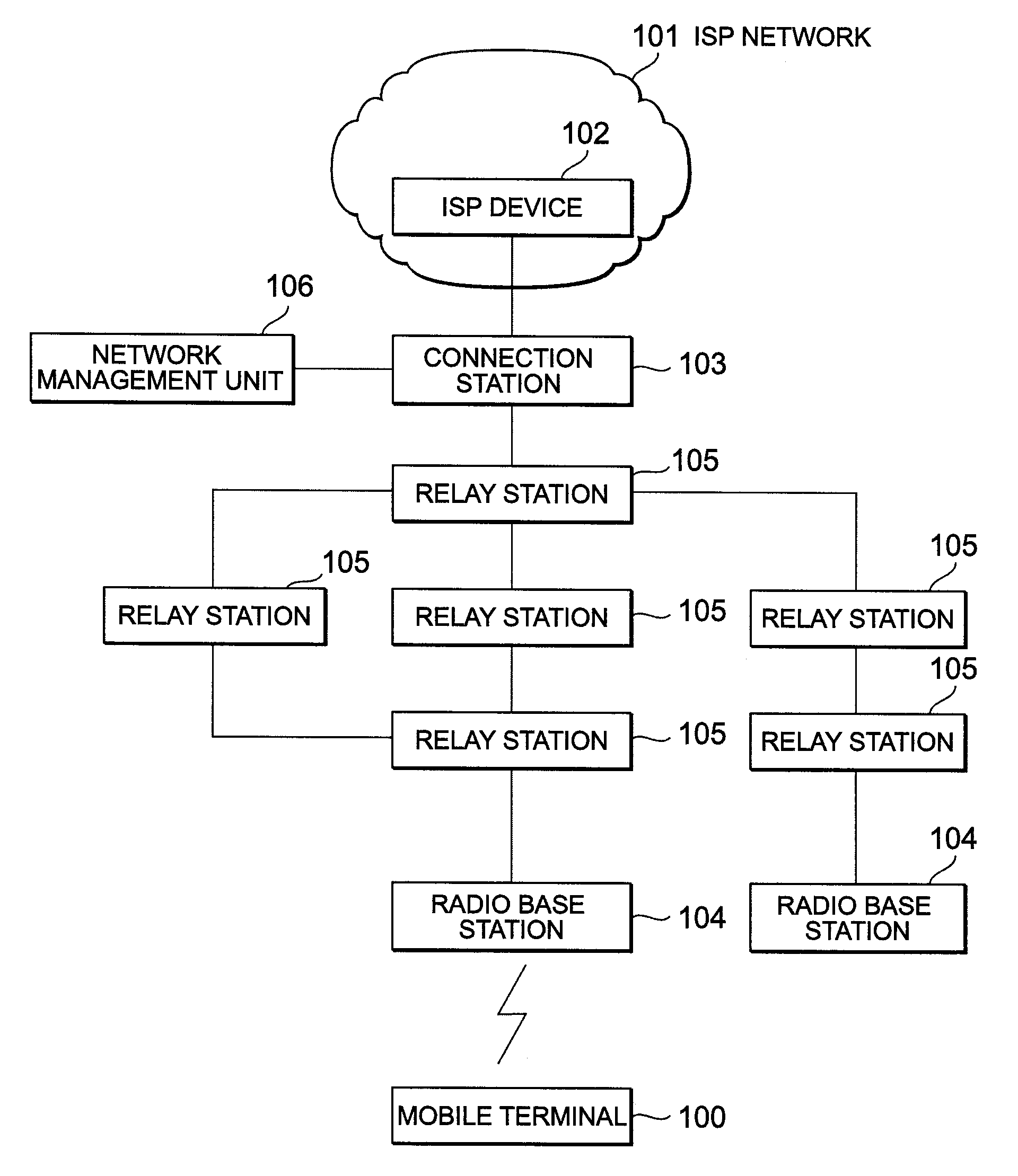
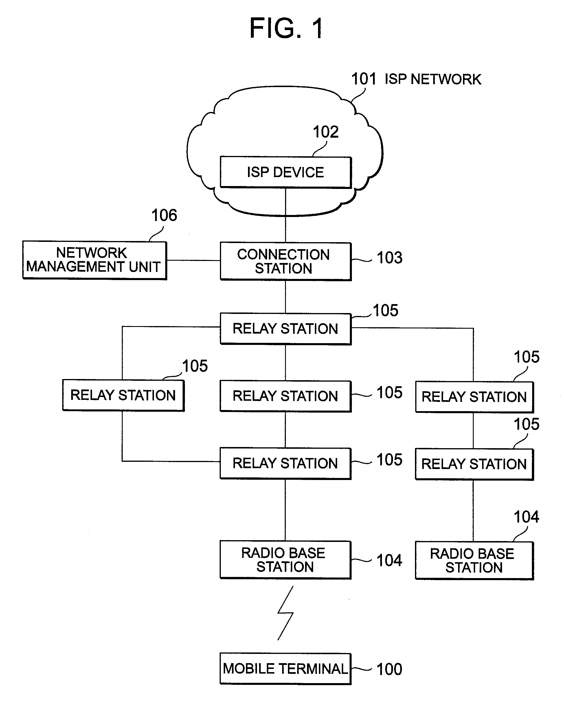
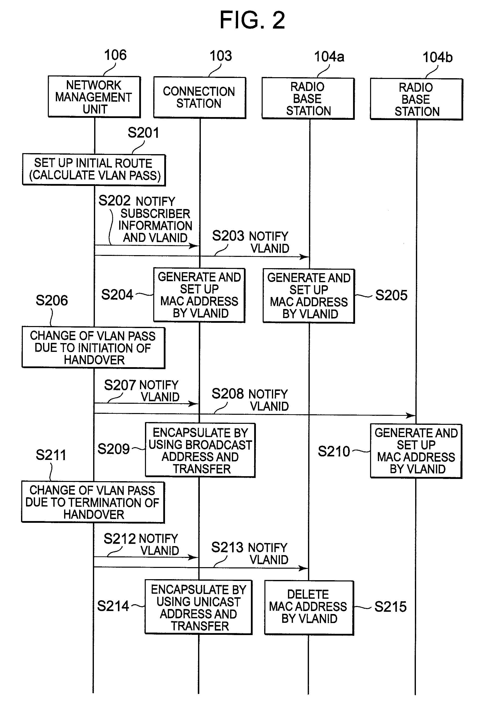
[0048] Description will be given below on an access network system, a connection station device, a radio base station device, and a packet loss reducing method in the embodiment of the present invention by referring to FIG. 1 to FIG. 14. FIG. 1 is a block diagram to show an arrangement of an access network system in an embodiment of the present invention. FIG. 2 is a block diagram to explain management of VLAN path by a network management unit in the access network system in the embodiment of the present invention. FIG. 3 to FIG. 5 each represents a block diagram to explain packet transfer before, during, and after handover of a mobile terminal in the access network system according to the embodiment of the present invention respectively.

[0049]FIG. 6A to FIG. 6C each represents a drawing to explain an encapsulated packet to be used in the access network system, the connection station device, the radio base station device, and the packet loss reducing method in the embodiment of the...


PUM


Abstract

The present invention discloses a technique to reduce packet loss during the handover of a mobile terminal and to eliminate wasteful consumption of band. According to this technique, a connection station 103 and a radio base station 104 where a mobile terminal 100 is connected generate a plurality of own MAC addresses based on identification information of the mobile terminal, and when the handover is started, a network management unit 106 makes up a point-to-multipoint VLAN path where VLAN path between new radio base station device and the connection station device is added to the VLAN path between previous radio base station device and the connection station device, and the connection station device adds a broadcast address, a MAC address of the connection station device, and an identification information of the mobile terminal to a packet received from the external IP network 101, and the packet is transferred via the point-to-multipoint VLAN path.

Description

TECHNICAL FIELD [0001] The present invention relates to an access network system, a connection station device, a radio base station device, and a packet loss reducing method for achieving mobility control in Wide-Area Ethernet™. BACKGROUND ART [0002] In the past, a mobile IP has been adopted for mobility control in IP network. The mobile IP is a technique, by which communication can be carried out by the same IP address regardless of the network, to which the mobile terminal is connected. A home agent in charge of the management of position of the mobile terminal (hereinafter, also referred as “HA”) receives a packet instead of the mobile terminal and transfers it to the mobile terminal. When the mobile terminal moves in a network during communication, the change of network address is notified and the destination of the transfer of the packet is changed. However, during the time from the change of the network address of the mobile terminal to the notification of the change to HA, th...

Claims


Application Information

Patent Timeline
Patent Type & Authority Applications(United States)
IPC IPC(8): H04Q7/00H04L12/28H04L12/46H04L12/70H04L12/701H04W8/26H04W28/04H04W36/00H04W36/36H04W40/34H04W40/36H04W84/12H04W88/08H04W92/00
CPCH04L12/4679H04W36/00H04W28/04H04W8/26
Inventor KAWAKAMI, TETSUYA
Owner PANASONIC CORP
Learn More