System and method for real-time jitter control and packet-loss concealment in an audio signal

a real-time jitter and packet-loss technology, applied in the field of packet-based audio signal reception and playback, can solve the problems of lag or delay in communication, receivers cannot wait for packets to be retransmitted, correctly ordered, or corrected without undue effect, and the signal quality and system performance is improved, so as to reduce delay and improve the quality of signals transmitted.

Inactive Publication Date: 2009-09-29
MICROSOFT TECH LICENSING LLC
View PDF23 Cites 29 Cited by
  • Summary
  • Abstract
  • Description
  • Claims
  • Application Information

AI Technical Summary

Benefits of technology

[0013]Jitter control and packet loss concealment are two well-known techniques for improving the quality of signals transmitted across lossy and delay prone packet-based networks such as the Internet and other conventional voice-based communications channels. Clearly, signal quality and system performance improves as a function of both reduced delay and reduced signal artifacts. Thus, to address the need for high quality audio jitter control and packet loss concealment, an “adaptive audio playback controller” is provided for performing automatic buffer-based adaptive jitter control and packet loss concealment for audio signals transmitted across a packet-based network as a function of buffer content. Further, the de-jittering and packet loss concealment processes described herein are compatible with most conventional codecs for decoding and providing a playback of audio signals.
[0017]In contrast, the adaptive audio playback controller described herein operates as a function of buffer content rather than packet receipt time. For example, unlike conventional stretching schemes, the audio playback controller begins stretching the contents of the buffer whenever a particular packet, e.g., packet n, has not arrived by the expected or scheduled time. In this case, the signal existing in the buffer is stretched until the delayed packet arrives, or until it is eventually declared “lost.” This differs from conventional stretching processes in that rather than immediately declaring a packet as a “late loss” when it is not received within a predetermined period of time, the contents of the buffer are stretched while simultaneously determining an appropriate time limit for declaring that packet to be a late loss as a function of the current buffer contents. Furthermore, the receipt of a subsequent packet (e.g., packet n+1, where packet n represents the expected packet) will change this time limit. Consequently, the adaptive audio playback controller provides a significantly increased packet receipt time prior to declaring a late loss for any given packet. As a result, packet “late loss” is significantly reduced, thereby resulting in a significantly reduced use of packet loss concealment processes for reducing artifacts in the signal, and a perceptibly cleaner signal playback. Further, and more importantly, the increased packet receipt time does not come at the cost of increased signal delay.
[0019]A second loss condition relates to receiving a subsequent packet prior to receiving the next expected packet in the transmission. Typically, this results from either packet inversion, or actual packet loss. As noted above, conventional schemes typically will generally ignore packet arrival order, and wait the maximum amount regardless of whether a subsequent packet has been received or not. In contrast, the adaptive audio playback controller reduces the time required to declare a late loss whenever a subsequent packet is received prior to receiving the expected packet. However, to minimize any declarations of “late loss” due to packet inversion, the adaptive audio playback controller still waits for some time before declaring a loss, even if a subsequent packet has already been received. On the other hand, since packet inversions are rare, the waiting is kept to a minimum, in order to avoid introducing additional artifacts in the signal. More specifically, the signal in the buffer will not be stretched beyond the period that the buffered signal would be stretched in the case where a packet loss would be declared, as noted above. Once that time has been reached, the packet n is declared as lost, and the packet loss concealment processes described herein are used to reduce or eliminate artifacts in the signal.
[0020]As noted above, signal stretching is used to compensate for delayed or lost packets. On the other hand, signal compression is used to address the case where the signal buffer has become too full, with a resulting increase in signal delay. Therefore, by compressing the signal contained in the buffer, playback time of the buffered signal is reduced, the buffer is at least partially emptied, and the signal playback delay is reduced. As described herein, when compressing the signal, it is typically a good idea to wait for a segment of speech where compression is expected to produce little or no artifacts, rather than simply compress the next segment to be played out. One simple solution is to compress only in between talk spurts. However, a better process considers how much compression is desired (i.e., how far behind in time signal playback is), and how easy it is to compress a particular segment while minimizing artifacts. Further, the need to compress the buffer implies that a long signal segment is in the buffer, and that therefore there is some freedom on where to compress the signal.
[0022]For example, compressing segments that represent speech, silence or simple noise, while avoiding compression of unvoiced segments or transients, produces a reconstructed signal having less perceivable artifacts. If sufficient compression cannot be accomplished by compressing segments representing speech, silence or simple noise, then non-transitional unvoiced segments are compressed in the manner described above. Finally, segments including transitions are compressed if sufficient compression can not be achieved through compression of the voiced segments or non-transitional unvoiced segments. This hierarchical approach to compression serves to limit perceivable artifacts in the reconstructed signal.
[0023]In view of the above summary, it is clear that the adaptive audio playback controller provides a unique system and method for providing buffer-based jitter control and packet loss concealment via adaptive stretching and compression of frames of a received audio signal while minimizing perceivable artifacts in a reconstruction of that signal. In addition to the just described benefits, other advantages of the system and method for providing buffer-based jitter control and packet loss concealment for a received audio signal will become apparent from the detailed description which follows hereinafter when taken in conjunction with the accompanying drawing figures.

Problems solved by technology

Conventional packet communication systems, such as the Internet or other broadcast network, are typically lossy.
Further, any delay in delivery time is usually variable.
However, for near real-time applications, such as, for example, voice-based communications systems across such packet-based networks, the receiver can not wait for packets to be retransmitted, correctly ordered, or corrected without causing undue, and noticeable, lag or delay in the communication.
Unfortunately, as the length of the buffer increases, playback of the signal increasingly lags real-time.
However, in systems such as real-time or two-way conversations, temporal lag resulting from the use of such buffers becomes increasing apparent, and undesirable, as the buffer length increases.
Unfortunately, the use of temporal stretching and compression techniques for frames in an audio signal often results in audible artifacts which may be objectionable to the human listener.
For example, as noted above, packet loss may occur when overly delayed packets are not received in time for playback.
Similarly, packet loss may also occur simply because the packet was never received.
However, when a packet does not arrive by the scheduled time, it is declared to be a late loss, and error concealment is then used to hide that loss.
Unfortunately, such schemes typically make packet-based decisions regarding whether a packet is to be declared as late loss.
Consequently, such schemes often declare packets to be a late loss when they are actually received in sufficient time that they could have been played as a part of the signal playback.
In contrast, the maximum buffer size is designed as a tradeoff between minimizing the probability that any given sample will need to be stretched, and the delay resulting from increased buffer size.
However, these schemes will declare a packet as a “late loss” when it is not received within a certain predetermined period of time.
Typically, this results from either packet inversion, or actual packet loss.
On the other hand, signal compression is used to address the case where the signal buffer has become too full, with a resulting increase in signal delay.

Method used


Image

  • System and method for real-time jitter control and packet-loss concealment in an audio signal
  • System and method for real-time jitter control and packet-loss concealment in an audio signal
  • System and method for real-time jitter control and packet-loss concealment in an audio signal

Examples


Embodiment Construction

[0032]In the following description of the preferred embodiments of the present invention, reference is made to the accompanying drawings, which form a part hereof, and in which is shown by way of illustration specific embodiments in which the invention may be practiced. It is understood that other embodiments may be utilized and structural changes may be made without departing from the scope of the present invention.

1.0 Exemplary Operating Environment:

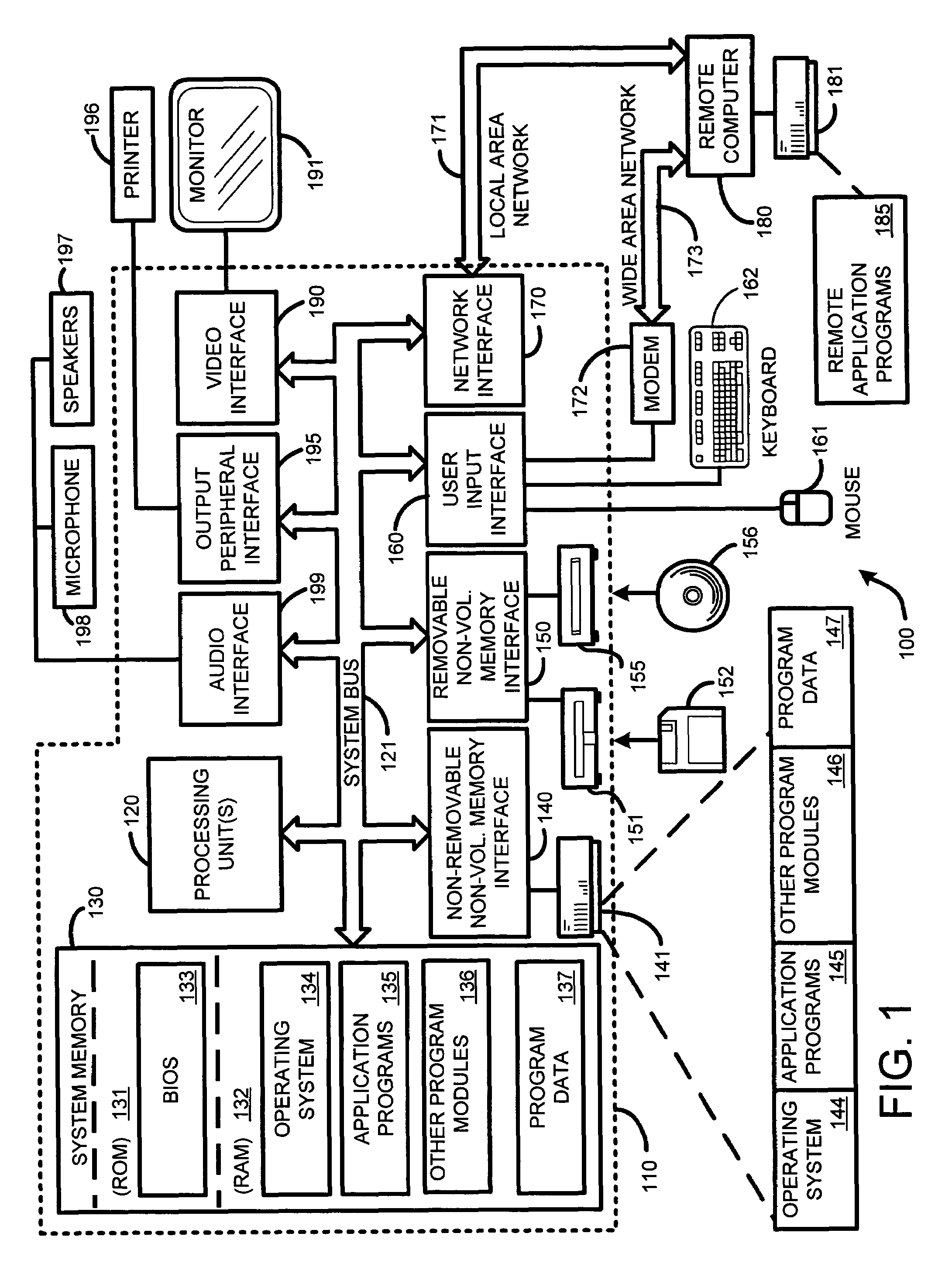
[0033]FIG. 1 illustrates an example of a suitable computing system environment 100 on which the invention may be implemented. The computing system environment 100 is only one example of a suitable computing environment and is not intended to suggest any limitation as to the scope of use or functionality of the invention. Neither should the computing environment 100 be interpreted as having any dependency or requirement relating to any one or combination of components illustrated in the exemplary operating environment 100.

[0034]The inve...


PUM


Abstract

An “adaptive audio playback controller” operates by decoding and reading received packets of an audio signal into a signal buffer. Samples of the decoded audio signal are then played out of the signal buffer according to the needs of a player device. Jitter control and packet loss concealment are accomplished by continuously analyzing buffer content in real-time, and determining whether to provide unmodified playback from the buffer contents, whether to compress buffer content, stretch buffer content, or whether to provide for packet loss concealment for overly delayed or lost packets as a function of buffer content. Further, the adaptive audio playback controller also determines where to stretch or compress particular frames or signal segments in the signal buffer, and how much to stretch or compress such segments in order to optimize perceived playback quality.

Description

BACKGROUND[0001]1. Technical Field[0002]The invention is related to receipt and playback of packet-based audio signals, and in particular, to a system and method for providing automatic jitter control and packet loss concealment for audio signals broadcast across a packet-based network or communications channel.[0003]2. Related Art[0004]Conventional packet communication systems, such as the Internet or other broadcast network, are typically lossy. In other words, not every transmitted packet can be guaranteed to be delivered either error free, on time, or even in the correct sequence. Further, any delay in delivery time is usually variable. If the receiver can wait for packets to be retransmitted, correctly ordered, or corrected using some type of error correction scheme, then the fact that such networks are inherently lossy and delay prone is not an issue. However, for near real-time applications, such as, for example, voice-based communications systems across such packet-based net...

Claims


Application Information

Patent Timeline
Patent Type & Authority Patents(United States)
IPC IPC(8): G10L19/04G10L11/06G10L21/04G10L19/00G10L25/93H04L12/56
CPCG10L19/005H04N21/4392H04N21/4398H04N21/4396H04N21/4394
Inventor FLORENCIO, DINEICHOU, PHILIPHE, LI-WEI
Owner MICROSOFT TECH LICENSING LLC
Why Eureka
Try Eureka