Two-channel, dual-mode, fiber optic rotary joint

a fiber optic rotary joint and dual-mode technology, applied in the direction of optics, instruments, optical light guides, etc., can solve the problems of electrical power requirements, difficult fabrication of facing lens systems, and loss due to crosstalk and overlap of signal paths, so as to reduce insertion loss, reduce insertion loss, and increase return loss.

Active Publication Date: 2007-09-20
PRINCETEL
View PDF5 Cites 74 Cited by
  • Summary
  • Abstract
  • Description
  • Claims
  • Application Information

AI Technical Summary

Benefits of technology

[0009] The first object of the present invention is to utilize the conventional collimators, micro-collimators, and reflecting surfaces to realize a two-pass fiber optical rotary joints which can simultaneously transmit optical signals through a single mechanical rotational interface with a very low-profile and compact structure for both single mode fiber and multi mode fiber.
[0010] Another object of the present invention to minimize the need for maintaining precise axial alignment between the rotating and non-rotating elements of a two channel fiber optic r

Problems solved by technology

The disadvantage of active FORJ is requirement for electrical power.
However, the transmission results in difficulties when it is desired to transmit two channels separately from each other through a single rotation interface.
The drawback of this design is that the losses due to

Method used


Image

  • Two-channel, dual-mode, fiber optic rotary joint
  • Two-channel, dual-mode, fiber optic rotary joint
  • Two-channel, dual-mode, fiber optic rotary joint

Examples


Embodiment Construction

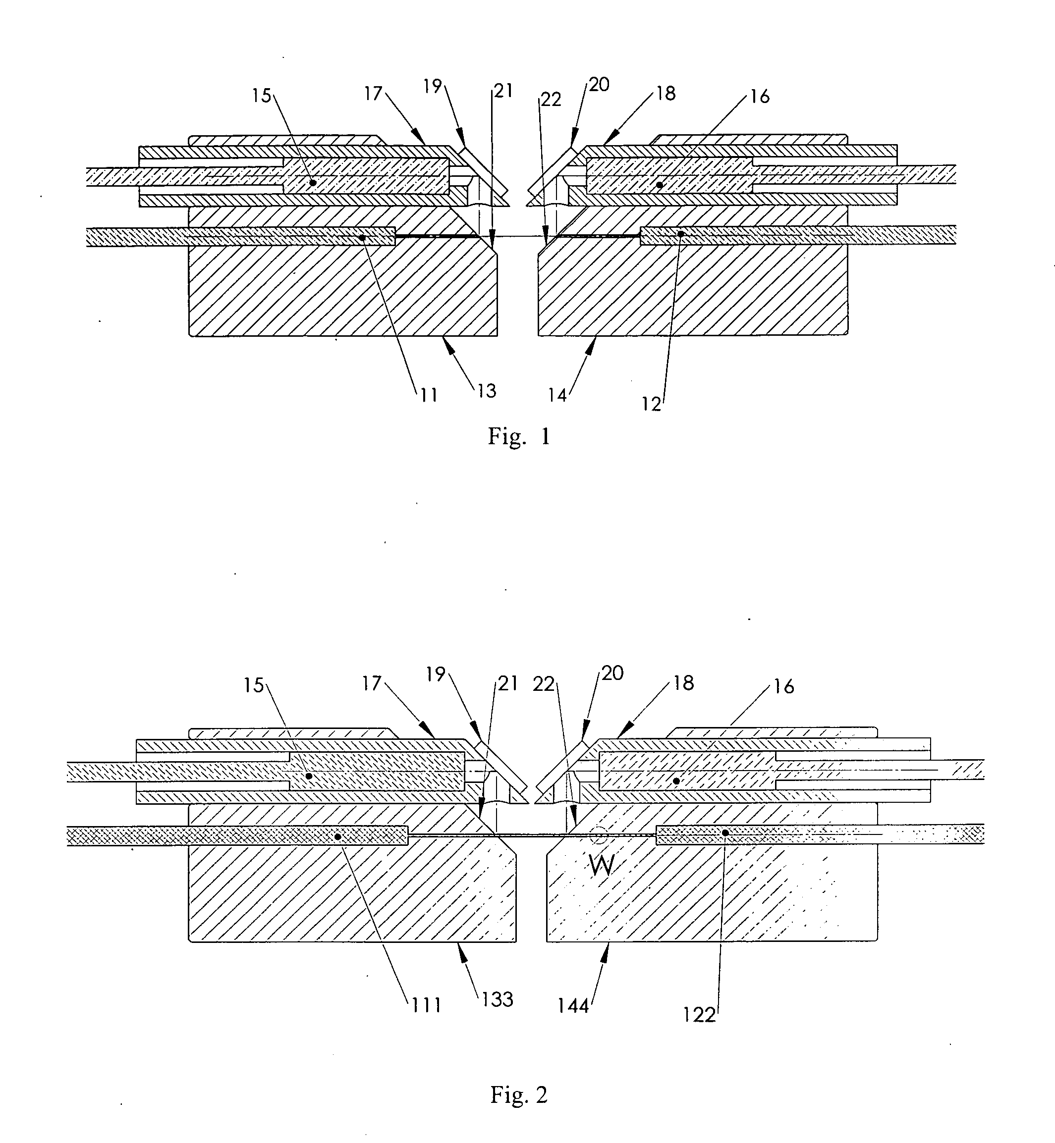
[0017]FIG. 1 illustrates a basic design of a two-channel fiber optical rotational interface. The holder 13 and 14 can be rotatable relative to each other. The axis of the rotation is the geometrical axis of the holder 13 and 14. The first channel of light pass consists of a micro-collimator 11 which is fixed on the axis of holder 13, and another micro-collimator 12 which is fixed on the axis of holder 14. The diameter of the micro-collimator is about 0.125 mm. Just like a single channel FORJ, the two micro-collimators are closely arranged opposite at their end section and the parallel ray of light emitted from one micro-collimator is easily transmitted to another micro-collimator through the rotational interface. The second channel of light pass includes conventional collimator 15 and 16, which are fitted inside of collimator housing 17 and 18 respectively, and reflecting surface 19 and 20. The collimator housing 17 and 18 are off -set on the holder 13 and 14 respectively, with thei...


PUM


Abstract

A two-channel fiber optical rotary joint has been invented in which optical signals can be transmitted simultaneously along two optical passes through a single mechanical rotational interface for both single mode fiber and multi mode fiber. The first channel of light path consists of a pair of micro-collimators, or a pair of fibers, co-axially fixed in 2 holders respectively. The light signal from one of micro-collimator, or fiber can be directly coupled into another micro-collimator, or fiber. The second channel of light path is off-axis arranged, including a pair of conventional collimators, a pair of first reflecting surfaces and a pair of second reflecting surfaces. The light signal emitted from one of the said conventional collimator will be reflected by one of the said first reflecting surface, one of the said second reflecting surface, another said second reflecting surface, and another said first reflecting surface, then coupled into another said conventional collimator. An index matching fluid is filled in the housing for lubrication and pressure compensation purposes.

Description

BACKGROUND OF THE INVENTION [0001] 1. Field of the Invention [0002] The invention is related to two channel fiber optic rotary joint in the field of optical transmission through a mechanical rotational interface. [0003] 2. Description of Related Art [0004] The Fiber optic Rotary Joint (FORJ) is the opto-mechanical device which allows uninterrupted transmission of an optical signal in a fiber guide through a rotational interface to a stationary apparatus. FORJ can be categorized as active and passive. An active FORJ consists of a light source on either rotor side or stator side and a photo detector on another side. The disadvantage of active FORJ is requirement for electrical power. The passive FORJ is intended to transfer optical signals from fiber to fiber without any electronic, or electrical units. The use of FORJ can be widely found in missile guidance systems, robotic systems, remotely operated vehicles (ROVs), oil drilling systems, sensing systems, and many other field applica...

Claims


Application Information

Patent Timeline
IPC IPC(8): G02B6/26
CPCG02B6/3604
Inventor ZHANG, BOYINGZHANG, HONG
Owner PRINCETEL
Why Eureka
Try Eureka