Eureka AIR delivers breakthrough ideas for toughest innovation challenges, trusted by R&D personnel around the world.

Medical image interpreting apparatus and cursor-moving method

a technology for medical images and cursors, applied in the field of technology for moving a cursor, can solve problems such as affecting the creation of interpretation reports and affecting the interpretation of images, and achieve the effect of reducing the burden of moving a cursor

Active Publication Date: 2007-09-20
TOSHIBA MEDICAL SYST CORP
View PDF8 Cites 11 Cited by
  • Summary
  • Abstract
  • Description
  • Claims
  • Application Information

AI Technical Summary

Benefits of technology

[0010]The purpose of the present invention is to provide technology that reduces the burden of moving a cursor in the task of interpreting a medical image.
[0012]According to the first embodiment of the present invention, as the cursor jumps to a desired destination of movement by slightly moving the cursor, it becomes possible to omit the intermediate operation of the pointing device. Thus, the burden of operating the pointing device is reduced, thereby preventing an operator's thoughts from being disrupted in creating an interpretation report, resulting in an enhancement of interpretation efficiency and a reduction in interpretation mistakes.
[0013]The initial movement information includes information on the origin of movement and the initial movement direction, whereby the information on the origin of movement may be regional information on the display screen divided into a plurality of regions. Furthermore, the region to which the origin of movement of the cursor belongs may be determined when the cursor begins to move via the pointing device. Accordingly, even if the origin of movement and the initial movement direction do not completely match according to the coordinating unit, the destination of movement becomes predictable, so the amount of the initial movement information and the information on the destination of movement to be stored is reduced, thereby easing the retrieving load, and the cursor may swiftly be jump-displayed.
[0014]Moreover, by detecting a specific operation for instructing a learning mode, from the status of movement of the cursor via the pointing device after the specific operation is detected, the initial movement information and the information on the destination of movement may be obtained and stored in the storage part. Thus, the initial movement and destination of movement of the cursor may be learned, and it becomes possible to enhance certainty of the predictable destination of movement.
[0016]According to the second embodiment, as the work incorporation destination and the data to be processed are both selected for the prescribed process, the reciprocating movement of the cursor between the work incorporation destination and the data is no longer required, so it becomes possible to reduce the operational volume of the pointing device. Therefore, the operational load of the pointing device is reduced, resulting in an enhancement in interpretation efficiency and a reduction in interpretation mistakes without disrupting an operator's thoughts in creating an interpretation report.
[0018]According to the third embodiment of the present invention, simply by moving the cursor into one area, the cursor appears in the other distant area. The intermediate pointing device operation may be omitted. Thus, the operational load of the pointing device is reduced, thereby preventing an operator's thoughts in creating an interpretation report from being disrupted, resulting in an enhancement of interpretation efficiency and a reduction in interpretation mistakes.

Problems solved by technology

The burden of moving the mouse cursor can disrupt the interpretation and creation of the interpretation report.

Method used


Image

  • Medical image interpreting apparatus and cursor-moving method
  • Medical image interpreting apparatus and cursor-moving method
  • Medical image interpreting apparatus and cursor-moving method

Examples


Embodiment Construction

[0052]Hereinafter, appropriate embodiments of a medical image interpreting apparatus related to the present invention are described in detail with reference to figures.

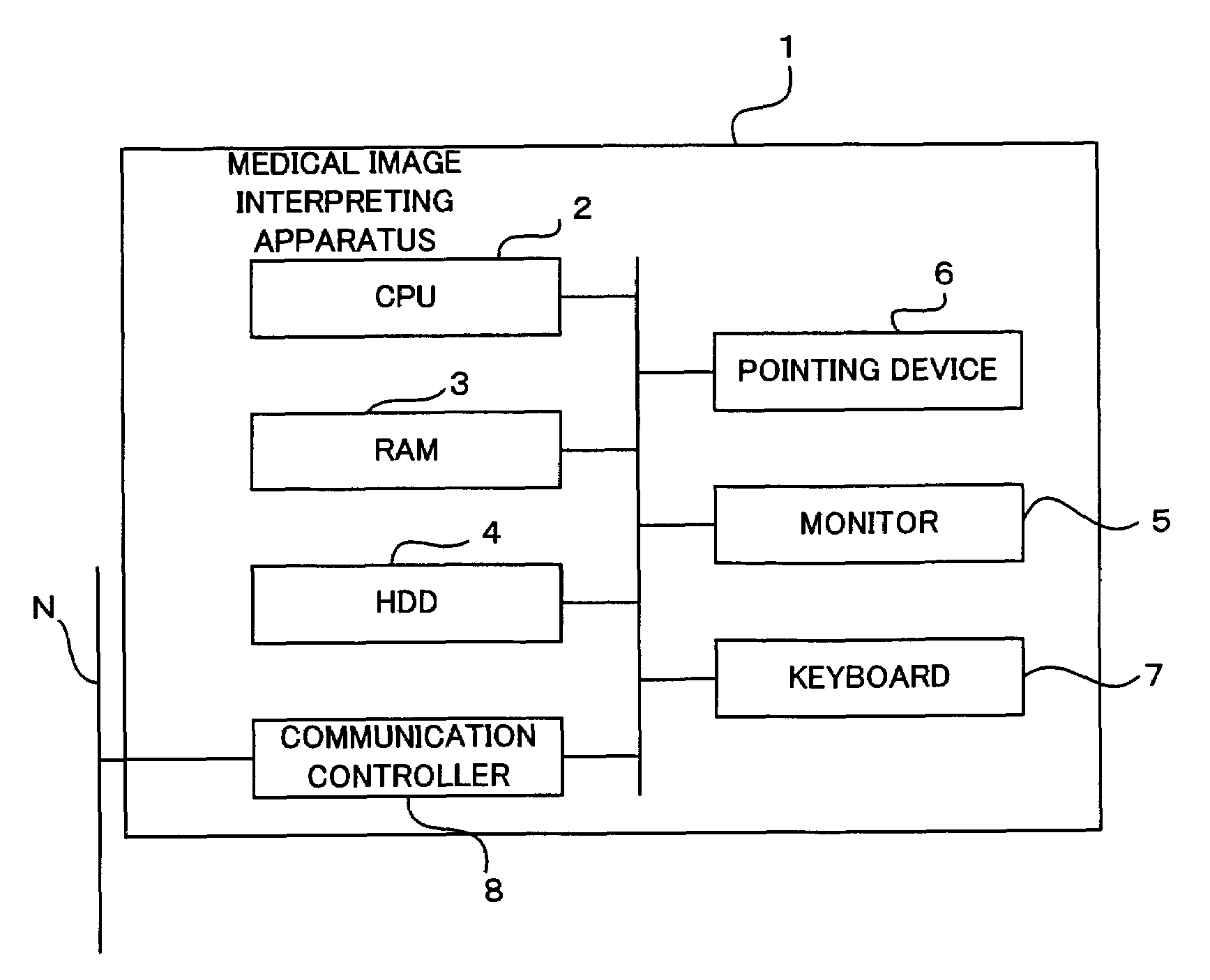
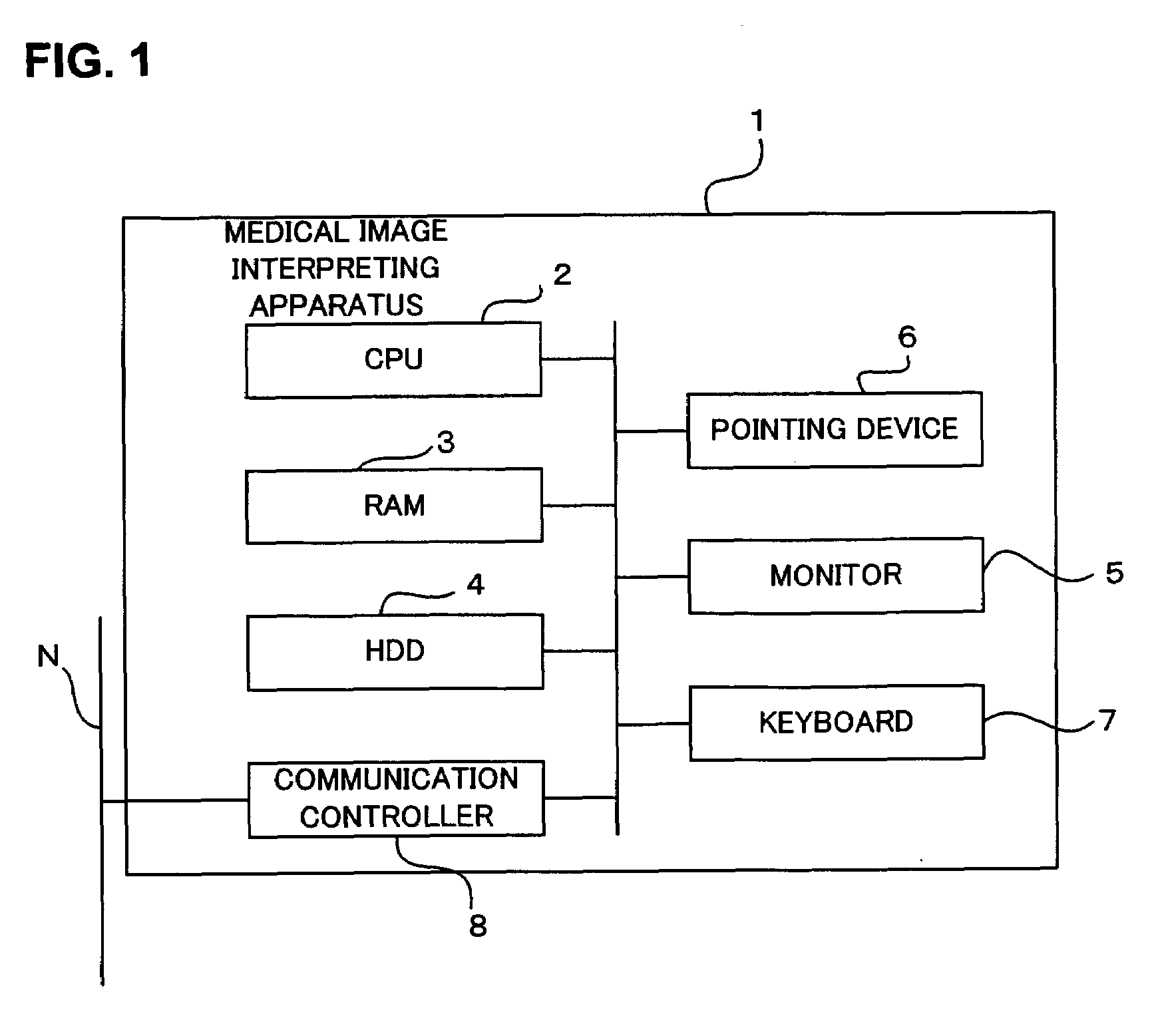
[0053]FIG. 1 is a block diagram showing components of a medical image interpreting apparatus related to the present embodiment. The medical image interpreting apparatus 1 comprises a computer internally provided with an arithmetic control part (CPU: Central Processing Unit) 2, a main storage part (RAM: Random Access Memory) 3, an external storage part (HDD: Hard Disk Drive) 4, and a communication controller 8, that are connected by a common line and are capable of mutual data input / output. Furthermore, as a man-made machine interface, a monitor 5, a pointing device 6, and a keyboard 7 are connected through an input / output controller that is not illustrated.

[0054]The arithmetic control part 2 interprets and executes programs for the calculation of data and control of devices. The main storage part 3 is a work area of t...


PUM


Abstract

In the medical image interpreting apparatus having a pointing device for moving a cursor, medical image, interpretation report, and cursor are displayed on a display screen, and initial movement information and information on the destination of movement of the cursor are linked and stored, via the pointing device when the cursor begins to move, said initial movement information relevant to the initial movement is retrieved to obtain the linked information on the destination of movement and the cursor is moved to the destination of movement indicated in the obtained information on the destination of movement. Due to this, just by slightly moving the cursor, the cursor jumps to the desired destination of movement, therefore, it becomes possible to omit an operation of the pointing device in between. Due to this, the operation load of the pointing device is reduced, thus preventing an operator's thought in creating an interpretation report from being destructed, and the enhancement in interpreting efficiency and the reduction of interpretation mistakes are achieved.

Description

BACKGROUND OF THE INVENTION[0001]1. Field of the Invention[0002]The present invention relates to a technology for moving a cursor when an interpretation report is being created.[0003]2. Description of the Related Art[0004]Nowadays, accompanied by upgraded medical acts, the diagnoses of patients are divided into different levels, and a specialist is involved at each level. In general, an image diagnosis is conducted procedurally as follows: image diagnosis request, image collection, interpretation, and determination of the treatment policy.[0005]For an image diagnosis request, a request form is submitted to a radiography department from the department requesting an examination such as the department of internal medicine. The request form includes the following items: the ID number of the patient, the patient's name, date of birth, sex, name of the department requesting the examination, name of the doctor requesting the examination, modality of the examination, subject of the examinat...

Claims


Application Information

Patent Timeline
IPC IPC(8): G05B15/00G09G5/00G06F3/00G06F3/038G16H10/60
CPCG06F3/038G06F3/0481G06F19/363G06F19/3406G06F19/3487G06F3/04812G16H10/20G16H40/63G16H15/00
Inventor KAWAKAMI, JUNNIWA, KENICHIMINAKUCHI, MAKIKONDO, TAKASHIMASUZAWA, TAKASHI
Owner TOSHIBA MEDICAL SYST CORP
Why Eureka
Eureka Blog
Learn More