Storage control device and data recovery method for storage control device

a storage control device and control device technology, applied in memory systems, redundant hardware error correction, instruments, etc., can solve the problems of affecting the response performance of the storage control device, affecting the recovery of stored content, and affecting the recovery of data using a parity disk. achieve the effect of efficient recovery of stored conten

Inactive Publication Date: 2007-09-20
HITACHI LTD
View PDF9 Cites 281 Cited by
  • Summary
  • Abstract
  • Description
  • Claims
  • Application Information

AI Technical Summary

Problems solved by technology

In the prior art that appears in Japanese Patent Application No. 2005-100259, the reliability of the storage control device is raised by using the spare disk but the relationship between preventative copying to the spare disk and the restoration of data using a parity disk is not adequately considered and provides a margin for improvement.
However, because the data restoration work is not synchronized with the preventative copying to the spare disk, data restoration work is performed with respect to all of the stored content of the disk in which the fault occurred irrespective of whether the preventative copying is complete.
Therefore, it takes a long time for the data restoration work to be completed and the response performance of the storage control device also drops.
In addition, although there are differences depending also on the RAID level, when a fault occurs in another disk during the period until completion of the data restoration work, data can no longer be restored.

Method used


Image

  • Storage control device and data recovery method for storage control device
  • Storage control device and data recovery method for storage control device
  • Storage control device and data recovery method for storage control device

Examples


first embodiment

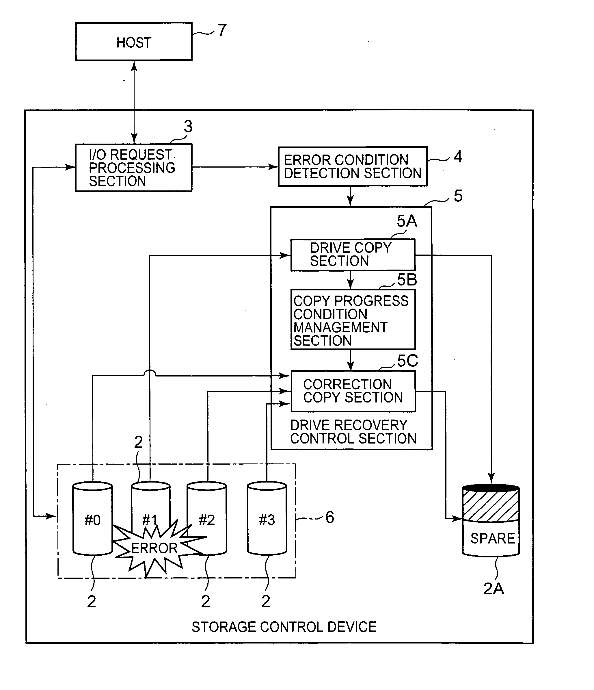
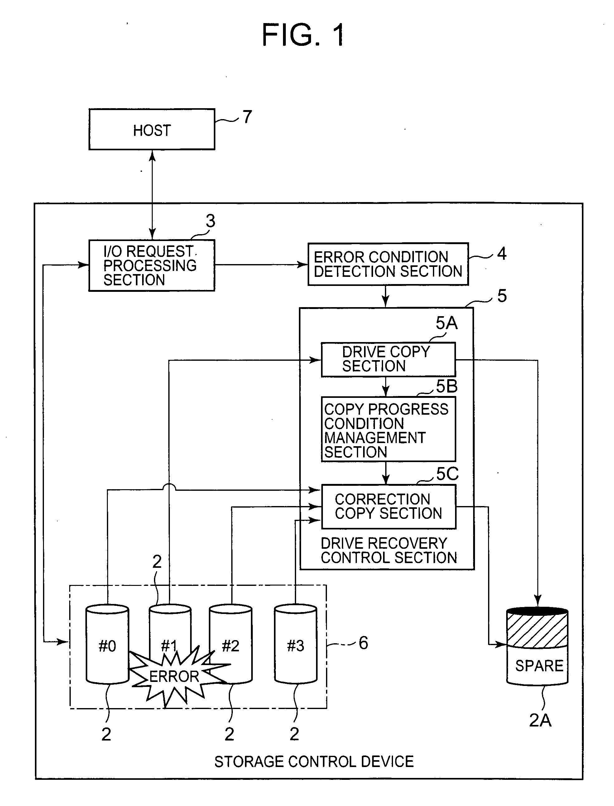
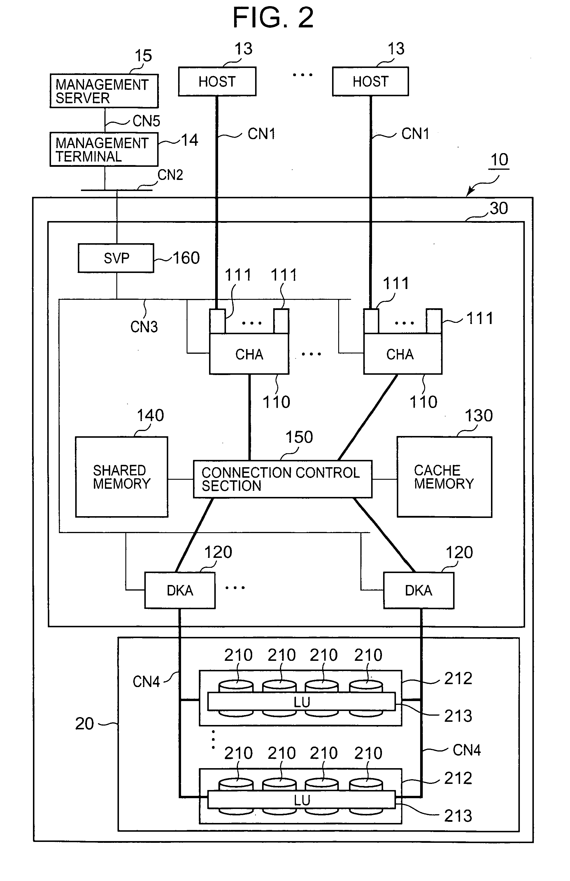
[0076]FIG. 2 is an explanatory diagram showing the overall constitution of the storage system including the storage control device 10 of this embodiment. The storage system can be constituted comprising the storage control device 10, a host 13, a management terminal 14, and a management server 15, for example. To explain the relationship with FIG. 1, the storage control device 10 corresponds to the storage control device 1 in FIG. 1, the host 13 corresponds to the host 7 in FIG. 1, the disk drive 210 corresponds to the disk drive 2 in FIG. 1, and the RAID group 212 corresponds to the RAID group 6 in FIG. 1.

[0077] First, the peripheral constitution of the storage control device 10 will be described, followed by the constitution of the storage control device 10. The host 13 is constituted as a computer device such as a personal computer, a server computer, a mainframe, an engineering workstation or the like, for example. The host 13 is connected to the storage control device 10 via t...

second embodiment

[0213] A second embodiment will now be described on the basis of FIGS. 19 to 21. Each of the following embodiments including this embodiment corresponds to a modified example of the first embodiment. In each of the following embodiments, a description of the constitution that is common to the above constitution is omitted and the focus of the description is on the characterizing parts. In this embodiment, when the recovery destination drive is updated by the host 13, the updated parts are managed by means of a bitmap. It is then judged whether the data to be processed has been recovered on the basis of the bitmap.

[0214]FIG. 19 is a portion of a flowchart for a case where a write command is received from the host 13 during the error production period. The flowchart corresponds with the flowchart shown in FIG. 17 and follows on from the flowchart shown in FIG. 16.

[0215] Therefore, the flowchart in FIG. 19 comprises steps (S535 to S544) common to the flowchart in FIG. 17. When the fo...

third embodiment

[0225] A third embodiment will now be described on the basis of FIG. 22. This embodiment further enhances the second embodiment and judges, based on the bitmap T15, whether the data to be processed has been recovered. FIG. 22 follows on from the flowchart shown in FIG. 19 via the association 1.

[0226]FIG. 22 is a flowchart for processing write commands. This flowchart corresponds to the flowchart shown in FIG. 16 and has the steps other than S525 and S530 in common. That is, in this embodiment, S590 and S591 are adopted instead of S525 and S530. In S590 and S591, logical block addresses are not compared and it is judged whether data are recovered data on the basis of the update flags of read target addresses.

[0227] That is, the controller 30 judges whether all the update flags relating to the block data for which a read request has been received have been set to “1” by referencing the bitmap T15 (S590, S591). When all the blocks to be read have update flags set to “1”, it is judged...


PUM


Abstract

The present invention efficiently recovers an error drive by suppressing futile copying. When the number of errors of the disk drive is equal to or more than a first threshold, data stored in the disk drive is copied to a spare drive by a drive copy section. When the number of errors of the disk drive is equal to or more than a second threshold prior to completion of the drive copy, the disk drive is closed, and a correction copy by a correction copy section is started in place of the drive copy. The correction copy section starts the correction copy from the position where the drive copy is interrupted by taking over the drive copy completion position (copy interrupt position) managed by a copy progress condition management section.

Description

CROSS-REFERENCE TO RELATED APPLICATIONS [0001] This application relates to and claims priority from Japanese Patent Application No. 2006-57337 filed on Mar. 3, 2006, the entire disclosure of which is incorporated herein by reference. BACKGROUND OF THE INVENTION [0002] 1. Field of the Invention [0003] The present invention relates to a storage control device and a data recovery method for the storage control device. [0004] 2. Description of the Related Art [0005] The storage control device generates RAID (Redundant Array of Independent Disks)-based redundant storage areas by using a plurality of disk drives such as hard disk drives, for example, and provides a host computer (‘host’ hereinbelow) with the storage areas. Even when a fault occurs in any of the disk drives in the storage areas made redundant through RAID, the storage capacity of the disk drive in which the fault occurred can be restored on the basis of the storage capacity stored in another disk drive. [0006] In the prior...

Claims


Application Information

Patent Timeline
Patent Type & Authority Applications(United States)
IPC IPC(8): G06F11/00
CPCG06F11/0727G06F11/076G06F11/2094G06F11/1662G06F11/1092
Inventor KATSURAGI, EIJUFUKUOKA, MIKIO
Owner HITACHI LTD
Why Eureka
Try Eureka