
Disinfection System

a technology of disinfection system and disinfection fluid, which is applied in the direction of maintenance for emmission reduction, energy-based wastewater treatment, space heating and ventilation, etc., can solve the problems of high cost and energy consumption of current disinfection system, ineffective technique, and inability to meet the needs of large-scale production and distribution, so as to reduce the effect of channelling

Inactive Publication Date: 2007-09-27
INFORM ENERGY
View PDF6 Cites 38 Cited by
  • Summary
  • Abstract
  • Description
  • Claims
  • Application Information

AI Technical Summary

Benefits of technology

[0024] The heat exchanger is typically formed from a convoluted pipe, or a coiled pipe. In the case of a coiled pipe, this is preferably adapted to reduce the effects of channelling within the pipe.

Problems solved by technology

However, current systems for disinfecting fluid tend to be expensive and energy inefficient, as well as having a short lifecycle due to corrosion of the holding tank, making the supply of large volumes of disinfected fluid an expensive process.
Whilst alternatives have been suggested, these techniques are also typically inefficient.
For example, in ensuring sufficient sanitation of sewer water, it is typical to use reverse osmosis which uses membranes that are very costly to operate and run while not fully reusing all of the waste water with significant losses in the treatment process.
A similar issue is encountered with ships ballast water.
This is a complex and time consuming process and incurs significant risks to the safety of the vessel.
In particular, when a ballast tank is empty this places undue strain on the hold and can lead to hull breaches.
In addition to this, whilst the water is being replenished the ship generally suffers from poor stability and can therefore capsize in heavy seas.
As a result of this, ship's captains often are unable to cycle the ballast water as required, often leading to contamination of different harbours.
In addition to this, it may be necessary to provide a degree of water purification, which again typically requires energy hungry apparatus.
Typically however such systems are also inefficient when used independently from other apparatus, and therefore unsuitable for many applications and further to the operating and environmental costs.

Method used


Image

  • Disinfection System
  • Disinfection System
  • Disinfection System

Examples


specific examples

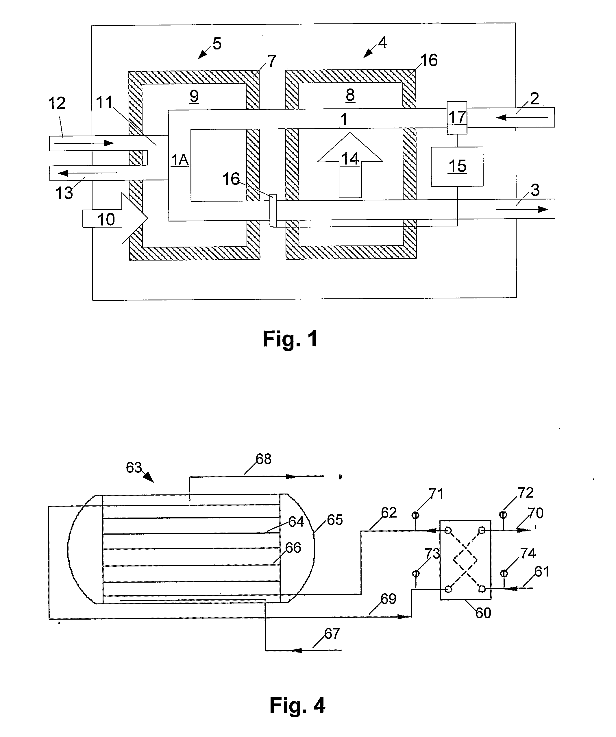
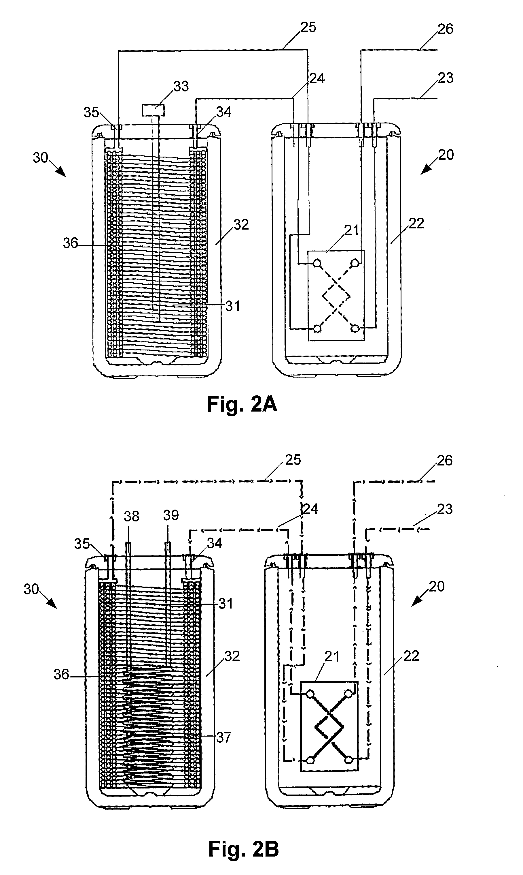
[0158] Examples of specific apparatus configurations for performing this will now be described with reference to FIGS. 2 to 4.

[0159] In particular, FIG. 2A shows a first configuration including a preheat tank 20, formed from a heat exchanger 21 provided in an insulated housing 22. The preheat tank 20 includes an inlet pipe 23 for receiving the fluid to be disinfected and an outlet pipe 24, for providing fluid at the first temperature. A second inlet pipe 25 is provided for receiving the disinfected fluid at the second temperature, with a second outlet pipe 26 being used to provide the disinfected fluid.

[0160] The outlet pipe 24, and the second inlet pipe 25, are connected to a disinfection tank 30 formed from a reverse acting calorifier. This may be formed from any suitable apparatus and generally includes an insulated housing for retaining heat, and a heat exchanger. In one example this is formed from a Rotex™ SC500 heat exchanger, although other apparatus may be used.

[0161] The...


PUM

PropertyMeasurementUnit
Temperatureaaaaaaaaaa
Lengthaaaaaaaaaa
Levelaaaaaaaaaa

Abstract

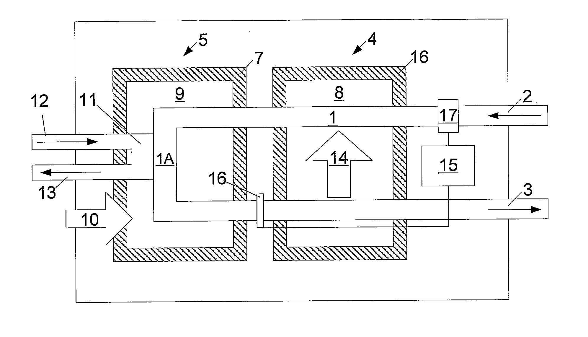
Apparatus for disinfecting fluid, the apparatus including a preheat heat exchanger (4) and a disinfection tank (5). The preheat exchanger heats the fluid to a first temperature and includes a first inlet for receiving the fluid (2), a first outlet for supplying preheated fluid at the first temperature, a second inlet for receiving disinfected fluid substantially at a second temperature and a second outlet for supplying the disinfected fluid (3). The disinfection tank heats the fluid to a second temperature and includes a heat source (10), an inlet for receiving the preheated fluid, a heat exchanger coupled to the inlet for heating the preheated fluid to a second temperature to thereby disinfect the fluid (11) and, an outlet coupled to the heat exchanger for providing the disinfected fluid to the second inlet of the preheat heat exchanger.

Description

BACKGROUND OF THE INVENTION [0001] The present invention relates to a method and apparatus for disinfecting fluids, and in particular, to apparatus for disinfecting fluids using heat treatment, as well as to apparatus for providing a combination supply, and in particular for supplying a combination of hot water, air conditioning and disinfected water. DESCRIPTION OF THE PRIOR ART [0002] The reference to any prior art in this specification is not, and should not be taken as, an acknowledgement or any form of suggestion that the prior art forms part of the common general knowledge. [0003] It is well known to provide for disinfection of fluids to destroy or inactivate organisms, viruses and pathogens in the fluids, by heating fluids to a predetermined temperature for a predetermined amount of time. Typically when it is desired to disinfect large or small volumes of fluid this is achieved either by heating the fluid in a holding tank or metallic tank [0004] However, current systems for ...

Claims


Application Information

Patent Timeline
IPC IPC(8): F28D7/00A61L2/00F28F1/00F25B27/02B01D3/00B63B11/04C02F1/02C02F1/14C02F1/16F25B29/00
CPCA61L2/04Y02T70/36B63B11/04B63J4/00B63J4/002C02F1/02C02F1/14C02F1/16C02F2103/005C02F2103/008C02F2201/009C02F2303/04F24D17/0073F28D7/0008F28D7/024F28D9/00F28D15/00F28D20/0034F28D21/0012Y02E60/142B01D3/007Y02W10/37Y02A20/212Y02E60/14Y02T70/00
Inventor STEWART, MURRAY KENNETH THOMASAITKEN, JOHN DAVID
Owner INFORM ENERGY
Learn More