Wind turbine generators having wind assisted cooling systems and cooling methods

a technology of wind turbine generators and cooling systems, which is applied in the direction of electric generator control, machines/engines, mechanical equipment, etc., can solve the problems of bulky, expensive, and difficult maintenance of traditional generator cooling equipmen

Active Publication Date: 2007-09-27
GENERAL ELECTRIC CO
View PDF14 Cites 81 Cited by
  • Summary
  • Abstract
  • Description
  • Claims
  • Application Information

AI Technical Summary

Problems solved by technology

Traditional generator cooling apparatus has been bulky, expensive and difficult to maintain.

Method used


Image

  • Wind turbine generators having wind assisted cooling systems and cooling methods
  • Wind turbine generators having wind assisted cooling systems and cooling methods
  • Wind turbine generators having wind assisted cooling systems and cooling methods

Examples


Embodiment Construction

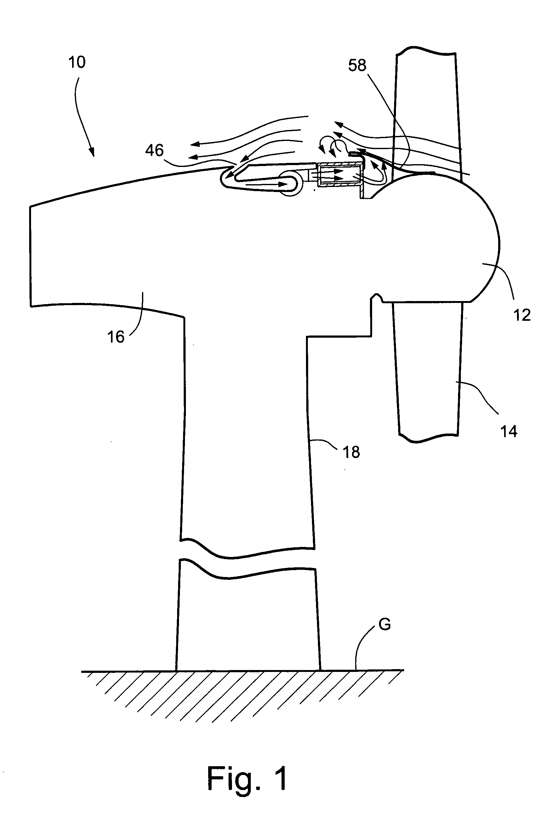
[0018] Referring to FIG. 1, there is schematically illustrated a wind turbine generator, generally designated 10, and including a rotating hub 12 mounting two or more airfoil shaped blades 14, a fixed nacelle 16 and a pylon 18 for structurally supporting the wind turbine generator hundreds of feet above ground level G.

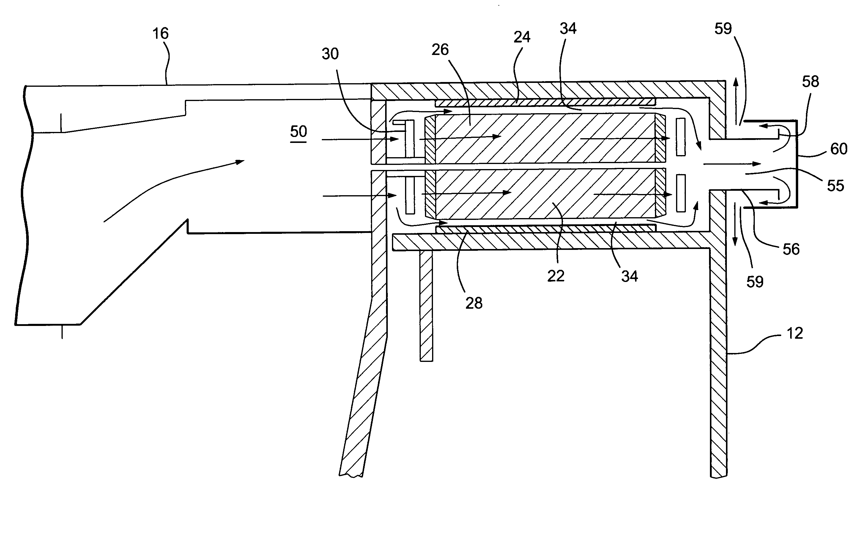
[0019] Referring to FIGS. 3 and 4, the nacelle 16 mounts a plurality of coils, or windings 22 forming part of the stator and a plurality of magnets or poles 24 about the rotor adjacent a forward part of the rotor near the hub 12. The illustrated present embodiment includes a double-sided generator having, as part of the stator, inner stator coils 22 and outer stator coils 26 and, as part of the rotor, outer magnets or poles 24 and inner magnets or poles 28. Thus the wind driven blades 14 drive the hub 12 which, in turn, rotates the outer and inner magnets 24 and 28 relative to the outer and inner stator coils 26 and 22 to generate electricity. It will be appreciated t...


PUM


Abstract

A wind generator includes: a nacelle; a hub rotatably carried by the nacelle and including at least a pair of wind turbine blades; and an electricity producing generator including a stator and a rotor carried by the nacelle. The rotor is connected to the hub and rotatable in response to wind acting on the blades to rotate the rotor relative to the stator to generate electricity. A cooling system is carried by the nacelle and includes at least one ambient air inlet port opening through a surface of the nacelle downstream of the hub and blades, and a duct for flowing air from the inlet port in a generally upstream direction toward the hub and in cooling relation to the stator.

Description

BACKGROUND OF THE INVENTION [0001] The present invention relates to wind assisted cooling for wind turbine generators and particularly relates to a cooling system which utilizes flow induced pressure and suction to receive cooling air from the ambient environment and routes the cooling air to the wind generator parts susceptible to thermal related degradation. [0002] Wind turbine generators typically stand on pylons hundreds of feet in the air. The generators include a hub mounting two or typically three airfoil blades which drive the generator. Within the nacelle mounting the hub, a rotor is rotated by the airfoil blades and hub. Rotation of the rotor either through a direct drive system or a gearbox causes relative rotation between magnetic poles and coils to generate electricity. In the direct drive generator, the rotor rotates at the same speed as the blades rotate and consequently a large radius is required to obtain the tangential velocity required to produce electricity. A ge...

Claims


Application Information

Patent Timeline
Patent Type & Authority Applications(United States)
IPC IPC(8): F03D9/00
CPCF03D9/002F05B2240/14F05B2260/20H02K7/1838Y02E10/725Y02E10/726H02K9/02F03D9/25F03D80/60Y02E10/72
Inventor BAGEPALLI, BHARATBARNES, GARYGADRE, ANIRUDDHAJANSEN, PATRICKBOUCHARD, CHARLESJARCZYNSKI, EMILGARG, JIVTESH
Owner GENERAL ELECTRIC CO
Why Eureka
Try Eureka