
Liquid crystal display device and display control method

a display device and liquid crystal technology, applied in static indicating devices, non-linear optics, instruments, etc., can solve the problems of unsatisfactory contrast, backlight consumption, and difficulty in smoothly displaying the motion of objects, so as to prevent a drop in contrast and improve the viewability of moving images.

Inactive Publication Date: 2007-09-27
TOSHIBA MATSUSHITA DISPLAY TECH
View PDF9 Cites 23 Cited by
  • Summary
  • Abstract
  • Description
  • Claims
  • Application Information

AI Technical Summary

Benefits of technology

[0014] An object of the present invention is to provide a liquid crystal display device and a display control method which can prevent a drop of contrast accompanying improvement of moving-image viewability.
[0016] According to a second aspect of the present invention, there is provided a method of controlling display of a liquid crystal display device which includes a display panel having a plurality of liquid crystal pixels, and an illuminative light source unit which illuminates the display panel, the method comprising: turning on and off the illuminative light source unit at a predetermined duty ratio every frame period for update of a video signal; and allowing each of the liquid crystal pixels to hold a variable pixel voltage that depends on the video signal for a gradation display period longer than a turn-on period of the illuminative light source unit and to hold a fixed pixel voltage that does not depend on the video signal for a non-gradation display period shorter than a turn-off period of the illuminative light source unit.
[0017] In the liquid crystal display device and the display control method, the variable pixel voltage that depends on the video signal is held by each of the liquid crystal pixels for the gradation display period which is longer than the turn-on period (i.e., a driving period to turn on light) of the illuminative light source unit, and the fixed pixel voltage that does not depend on the video signal is held by each of the liquid crystal pixels for the non-gradation display period which is shorter than the turn-off period (i.e., a driving stop period to turn off light, or a slightly driving period to bring about a substantial light-off state) of the illuminative light source unit. That is, when the minimum gradation luminance level of the liquid crystal pixel is lowered by reducing the duty ratio of the illuminative light source unit, the maximum gradation luminance level of the liquid crystal pixel might be lowered. However, since the non-gradation display period is shortened, the gradation display period continues even after the illuminative light source unit turns off. Therefore, there is effectively utilized afterglow emitted from the illuminative light source unit for a while after the illuminative light source unit turns off, and the luminance level of the liquid crystal pixel with respect to the maximum gradation can be raised. In a case where the illuminative light source unit is constituted of a plurality of light sources, the luminance level of the liquid crystal pixel with respect to the maximum gradation can further be raised by effectively utilizing the light from the adjacent light source. Therefore, there is compensation for an influence due to a difference between an optical response of the liquid crystal pixel and an optical response of the illuminative light source or an influence occurring in a case where the illuminative light sources are allowed to blink with different phases, and it is possible to prevent a drop of contrast accompanying improvement of moving-image viewability.

Problems solved by technology

In the meantime, since the liquid crystal display panel is a hold-type display device that holds a display state until updating of image data, it is difficult to smoothly display the motion of an object, owing to the effect of retinal persistence occurring on a viewer's vision in moving-image display.
In addition, since the conventional black insertion driving is performed by constantly turning on the backlight, this backlight consumes power even in the black insertion period, and further inhibits a black display state from being brought to a complete black state having a luminance of zero.
Accordingly, the contrast can also be improved to a certain degree, but a satisfactory contrast has not been obtained owing to an influence of a difference between an optical response of the liquid crystal pixel and an optical response of the backlight or an influence occurring in a case where a plurality of backlight sources are arranged as the backlight and allowed to blink with different phases.

Method used


Image

  • Liquid crystal display device and display control method
  • Liquid crystal display device and display control method
  • Liquid crystal display device and display control method

Examples


Embodiment Construction

[0026] There will be described hereinafter a liquid crystal display device in one embodiment of the present invention with reference to the accompanying drawings.

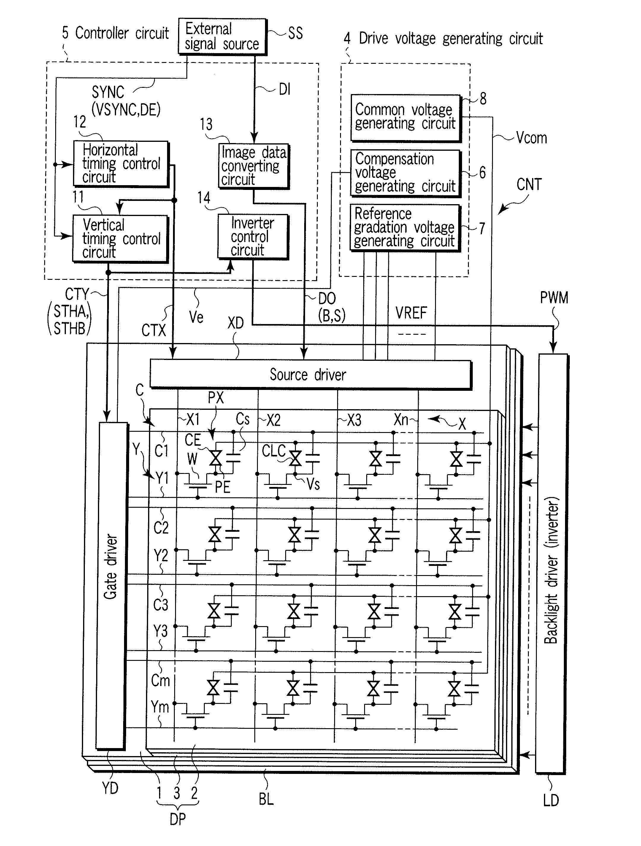
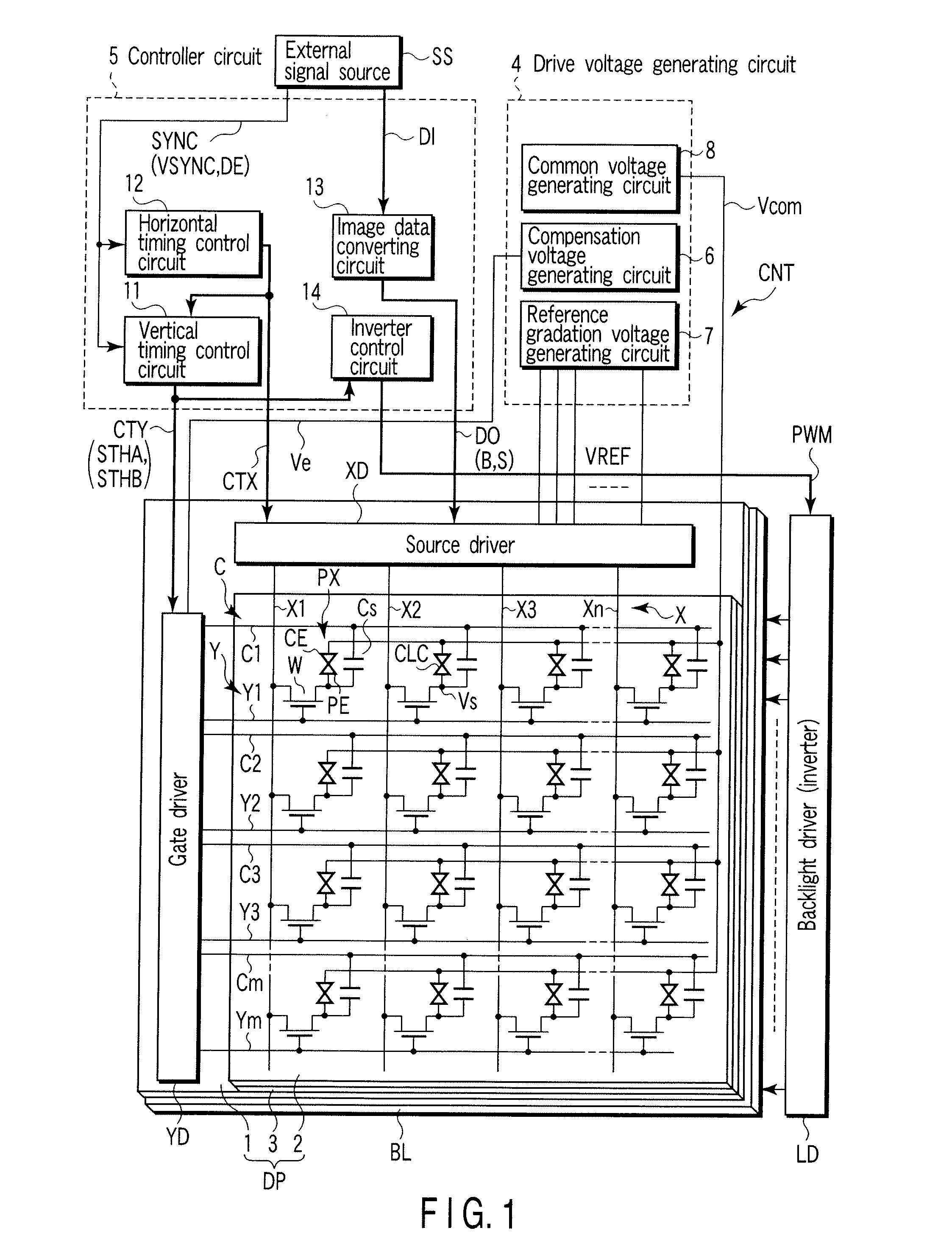
[0027]FIG. 1 schematically shows the circuit configuration of this liquid crystal display device. The liquid crystal display device includes a liquid crystal display panel DP; a backlight BL which illuminates the display panel DP; and a display control circuit CNT which controls the display panel DP and the backlight BL. The liquid crystal display panel DP has a structure in which a liquid crystal layer 3 is held between an array substrate 1 and a counter-substrate 2 as a pair of electrode substrates. The liquid crystal layer 3 includes, as a liquid crystal material, liquid crystal molecules which are transitioned in advance from a splay alignment to a bend alignment for, for example, a normally white display operation, and are prevented from inverse-transition from the bend alignment to the splay alignment by a periodical...


PUM


Abstract

A liquid crystal display device includes a display panel having liquid crystal pixels, and a backlight which illuminates the display panel. In particular, this liquid crystal display device further includes a light source driving unit which turns on and off the backlight at a predetermined duty ratio every frame period for update of a video signal, and a panel driving unit which allows each of the liquid crystal pixels to hold a variable pixel voltage that depends on the video signal for a gradation display period longer than a turn-on period of the backlight and which allows each of the liquid crystal pixels to hold a fixed pixel voltage that does not depend on this video signal for a non-gradation display period shorter than a turn-off period of the backlight.

Description

CROSS-REFERENCE TO RELATED APPLICATIONS [0001] This is a Continuation Application of PCT Application No. PCT / JP2005 / 022113, filed Dec. 1, 2005, which was published under PCT Article 21(2) in Japanese. [0002] This application is based upon and claims the benefit of priority from prior Japanese Patent Application No. 2004-350326, filed Dec. 2, 2004, the entire contents of which are incorporated herein by reference.BACKGROUND OF THE INVENTION [0003] 1. Field of the Invention [0004] The present invention relates to a liquid crystal display device and a display control method in which, for example, one frame period is divided into a gradation display period and a non-gradation display period, variable-gradation display is performed in response to a video signal in the gradation display period, and display of a fixed gradation such as black or an intermediate gradation is performed in the non-gradation display period. [0005] 2. Description of the Related Art [0006] A flat-panel display de...

Claims


Application Information

Patent Timeline
IPC IPC(8): G09G3/36
CPCG09G3/3648G09G2310/0237G09G2310/024G09G3/342G09G2320/064G02F2001/133612G09G2320/0261G02F1/133612G02F1/133G09G3/20G09G3/36
Inventor OKITA, MITSUTAKANISHIYAMA, KAZUHIROSUZUKI, DAIICHIARAKI, SHIGESUMI
Owner TOSHIBA MATSUSHITA DISPLAY TECH
Learn More