Methods of range selection for positioning marine seismic equipment

Inactive Publication Date: 2007-09-27
WESTERNGECO LLC
View PDF36 Cites 15 Cited by
  • Summary
  • Abstract
  • Description
  • Claims
  • Application Information

AI Technical Summary

Benefits of technology

[0005] Accordingly, methods for selecting an accurate signal arrival by a receiver from a pinger for accurately positioning seismic equipment are prov

Problems solved by technology

Reflections from a boundary, the sea-surface or sea floor, travel a longer distance than the direct arrival signals and are therefore subject to a time delay relative to the direct arrival.
Tracking the reflections rather than the direct arriva

Method used


Image

  • Methods of range selection for positioning marine seismic equipment
  • Methods of range selection for positioning marine seismic equipment

Examples


Example

[0013] Refer now to the drawings wherein depicted elements are not necessarily shown to scale and wherein like or similar elements are designated by the same reference numeral through the several views.

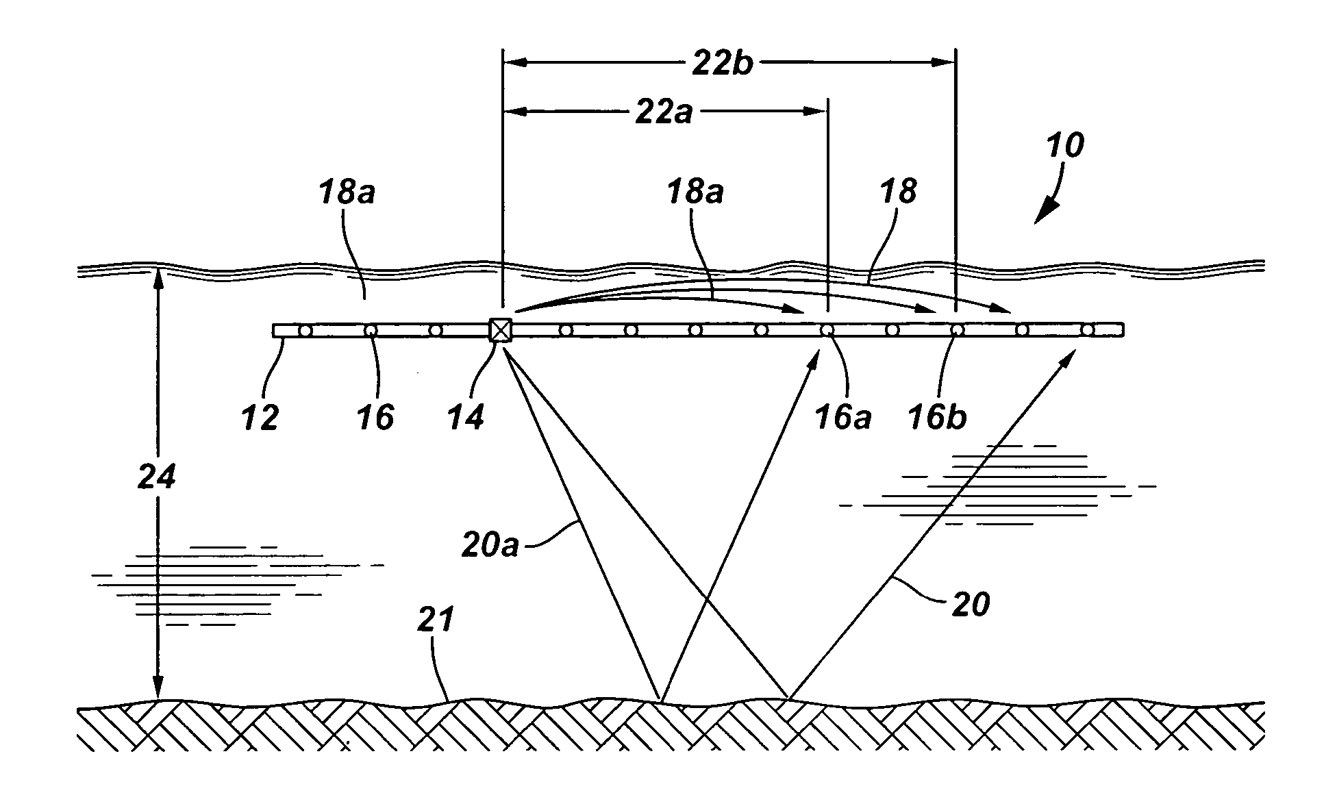
[0014]FIG. 1 is an illustration of an embodiment of a spread of seismic equipment of a seismic positioning system of the present invention, generally designated by the numeral 10, illustrated as a shallow water geometry in 2D. Seismic spread 10 includes at least one streamer 12 having at least one pinger 14 and a plurality of receivers 16. As is well known in the art, a seismic spread commonly includes multiple streamers 12 each of which includes a plurality of pingers 14 and receivers 16. The geographic location of at least one point in the spread is typically known from convention means, such as a global positioning system. For example, the geographic location of pinger 14 may be determined by a global positioning system.

[0015] An acoustic transmitter 14, also referred to as a pin...


PUM


Abstract

A method for selecting a signal arrival for determining an accurate position of seismic equipment includes the steps of transmitting a signal from a pinger; predicting a direct arrival and a reflected arrival of the signal at a receiver, wherein each arrival is the time between the transmission of the signal to reception of the signal; measuring arrivals of the signal at the receiver; selecting the measured signal arrival that is similar to the predicted direct arrival as a preliminary signal arrival; defining a confidence interval for the actual direct arrival of the signal based on the predicted direct arrival and the predicted reflected arrival; and finalizing the signal arrival, wherein the selected preliminary signal arrival is the finalized signal arrival if it is within the confidence interval.

Description

FIELD OF THE INVENTION [0001] The present invention relates in general to methods for determining the position of seismic spreads and more particularly to a model based range selection method for determining the geometric configuration and position of seismic equipment in a seismic spread. BACKGROUND [0002] In underwater acoustic navigation of a marine seismic spread, ranges are measured to determine the geometric relationship between the seismic equipment and a position of the seismic equipment and the spread. An accurate range is the travel time of the direct arrival of a signal from a pinger by a particular receiver. The direct arrival is the acoustic signal traveling along the path of shortest travel time in the water column without being influenced by the reflection from a boundary. Reflections from a boundary, the sea-surface or sea floor, travel a longer distance than the direct arrival signals and are therefore subject to a time delay relative to the direct arrival. Tracking...

Claims


Application Information

Patent Timeline
IPC IPC(8): G01V1/38
CPCG01S5/26G01V1/38G01V1/3835G01V1/3817
Inventor FRIVIK, SVEIN ARNECOMBEE, LEENDERT
Owner WESTERNGECO LLC
Why Eureka
Try Eureka