Normalization and calibration of microphones in sound-intensity probes

a technology of sound intensity and calibration, which is applied in the direction of transducer details, electrical transducers, electrical apparatus, etc., can solve the problems that calibration and phase-matching at a single frequency cannot be used to make corrections to provide substantially identical responses between microphones, and the lower limit cannot be used to achieve accurate measurements of sound intensity

Inactive Publication Date: 2007-09-27
HICKLING ROBERT
View PDF10 Cites 8 Cited by
  • Summary
  • Abstract
  • Description
  • Claims
  • Application Information

AI Technical Summary

Benefits of technology

[0021] The normalizer-calibrator system is used to determine the transfer function between each microphone of a sound-intensity probe and the comparison microphone. When measuring sound intensity, the spectral form of the sound pressure measured at each microphone in a probe is multiplied by the corresponding transfer function. This makes the microphones have

Problems solved by technology

There is also a lower limit due to possible error from phase mismatch of the microphones at lower frequencies.
Hence calibration and pha

Method used


Image

  • Normalization and calibration of microphones in sound-intensity probes
  • Normalization and calibration of microphones in sound-intensity probes
  • Normalization and calibration of microphones in sound-intensity probes

Examples


Embodiment Construction

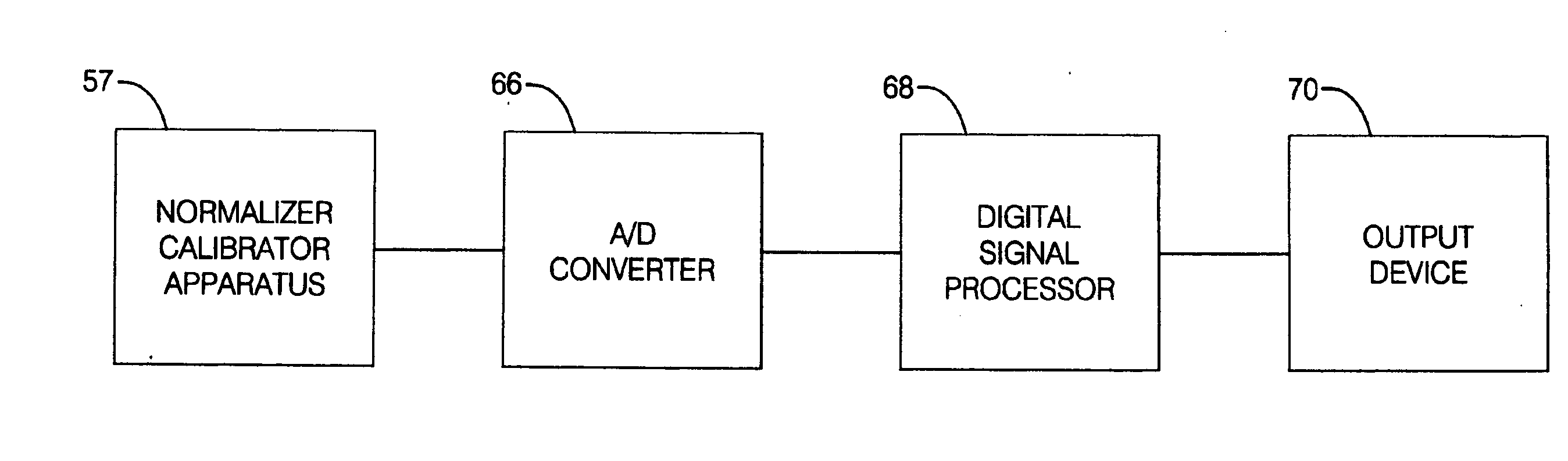
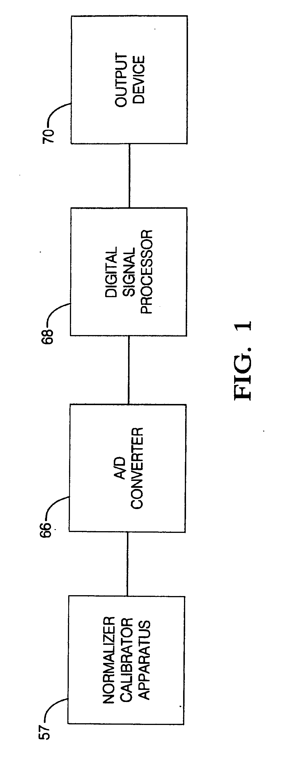
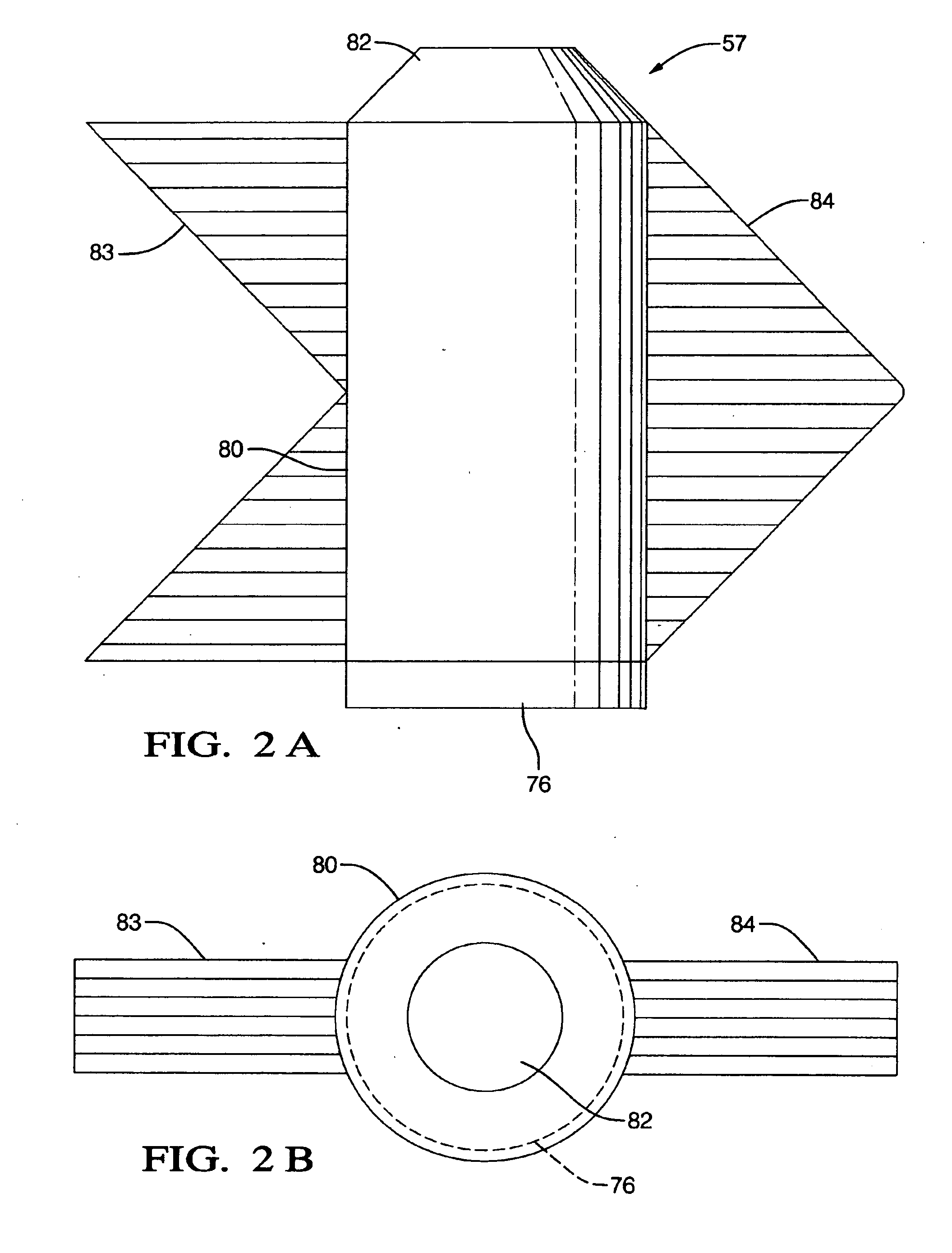
[0032]FIG. 1 shows a block diagram of the normalizer-calibrator system. Signals from the normalizer-calibrator apparatus 57 are passed through an A / D converter 66 to the digital signal processor 68 which determines the transfer functions between individual microphones of a sound-intensity probe and a comparison microphone. Results are displayed using the output device 70. FIG. 2 depicts elevation and plan views of the normalizer-calibrator apparatus 57. This consists of a tube 80 with a loudspeaker 82 at one end and a fixture 76 for holding the microphones from the sound-intensity probe and the comparison microphone at the other end. All the microphones are flush with the inner surface of the fixture where they are simultaneously exposed to plane waves proceeding down the normalizer-calibrator tube from the speaker. The speaker is controlled by the digital signal processor. In general it emits pseudo-random white noise or other broadband time-invariant or stationary signals. Standin...


PUM


Abstract

A system for normalizing and calibrating the microphones of a sound-intensity probe or a composite of such probes, with respect to a stable comparison microphone with known acoustical characteristics. Normalizing and calibrating are performed using an apparatus 57 consisting of a tube with a loudspeaker inserted in one end and a fixture for holding the microphones of the probe together with the comparison microphone in the other end. The comparison microphone has known acoustical characteristics supplied by the manufacturer. Two banks of quarter-wave resonators 83 and 84 are attached to the side of the tube to absorb standing waves. The sound-intensity probe can be either a two-microphone probe used for measuring a single component of the sound-intensity vector or a probe with four microphones in the regular tetrahedral arrangement used for measuring the full sound-intensity vector. The microphones in the probe are made to have a substantially identical response with the comparison microphone by determining the transfer functions between the microphones and the comparison microphone. The transfer functions and known acoustical characteristics of the comparison microphone are then used to correct the pressure measurements by the microphones, when they are used to measure sound intensity. This ensures that the sound-intensity measurements are accurate and that there is essentially no bias in determining the direction to a sound source from the direction of the sound-intensity vector.

Description

[0001] THIS APPLICATION IS A CONTINUATION-IN-PART OF U.S. patent application ENTITLED “ACOUSTIC MEASUREMENT METHOD AND APPARATUS” Ser. No. 10 / 396,541, FILED 2003, Mar. 25, AND OF CONTINUATION-IN PART ENTITLED “SOUND SOURCE LOCATION AND QUANTIFICATION USING VECTOR PROBES” Ser. No. 10 / 746,763 FILED 2003, Dec. 26, BY ROBERT HICKLING THE PRESENT INVENTOR.TECHNICAL FIELD [0002] This invention relates to a means and method for the normalization and calibration of the microphones in sound-intensity probes. BACKGROUND OF THE INVENTION Sound-Intensity Probes [0003] The sound-intensity vector is the time average of sound-power flow per unit area expressed in spectral form. [0004] The sound-intensity probe that is currently in greatest use consists of two microphones that measure a single component of the vector along a line joining the microphone centers. Usually the measurement is made in a direction perpendicular to a surface, such as a hypothetical surface enclosing a sound source or the ...

Claims


Application Information

Patent Timeline
IPC IPC(8): H04R3/00H04R1/02
CPCH04R3/04H04R29/004H04R19/016
Inventor HICKLING, ROBERT
Owner HICKLING ROBERT
Why Eureka
Try Eureka