Fixing device and image forming apparatus having the same

Inactive Publication Date: 2007-09-27
RICOH KK
View PDF6 Cites 21 Cited by
  • Summary
  • Abstract
  • Description
  • Claims
  • Application Information

AI Technical Summary

Benefits of technology

[0010] With the foregoing in mind, an object of the present invention is to provide a fixing device and an image forming apparatus having the same, which can achieve good recording medium separation performan

Problems solved by technology

However, the belt nip-type fixing device of the above-mentioned publication is deficient in that the recording medium outlet side of the nip portion of the heating roller surface is locally elastically deformed, and a velocity difference occurs between the front surface and rear surface of the recording medium at the part subjected to deformation by this local elastic deformation, making image misalignment more apt to occur.
Further, since applying pressure to the heating roller using a hard pressure pad member creates a nip shape having a locally small curvature a

Method used


Image

  • Fixing device and image forming apparatus having the same
  • Fixing device and image forming apparatus having the same
  • Fixing device and image forming apparatus having the same

Examples


Embodiment Construction

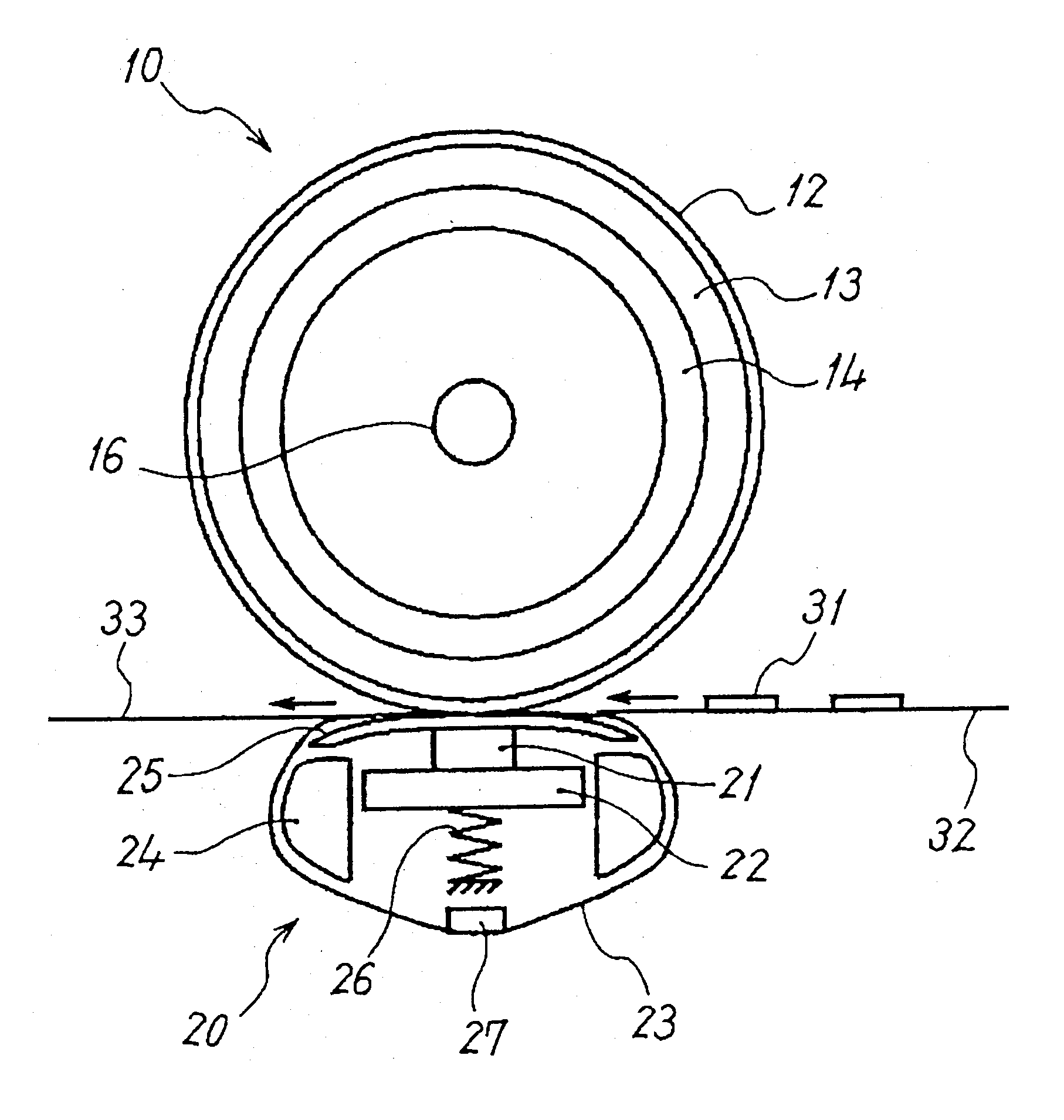
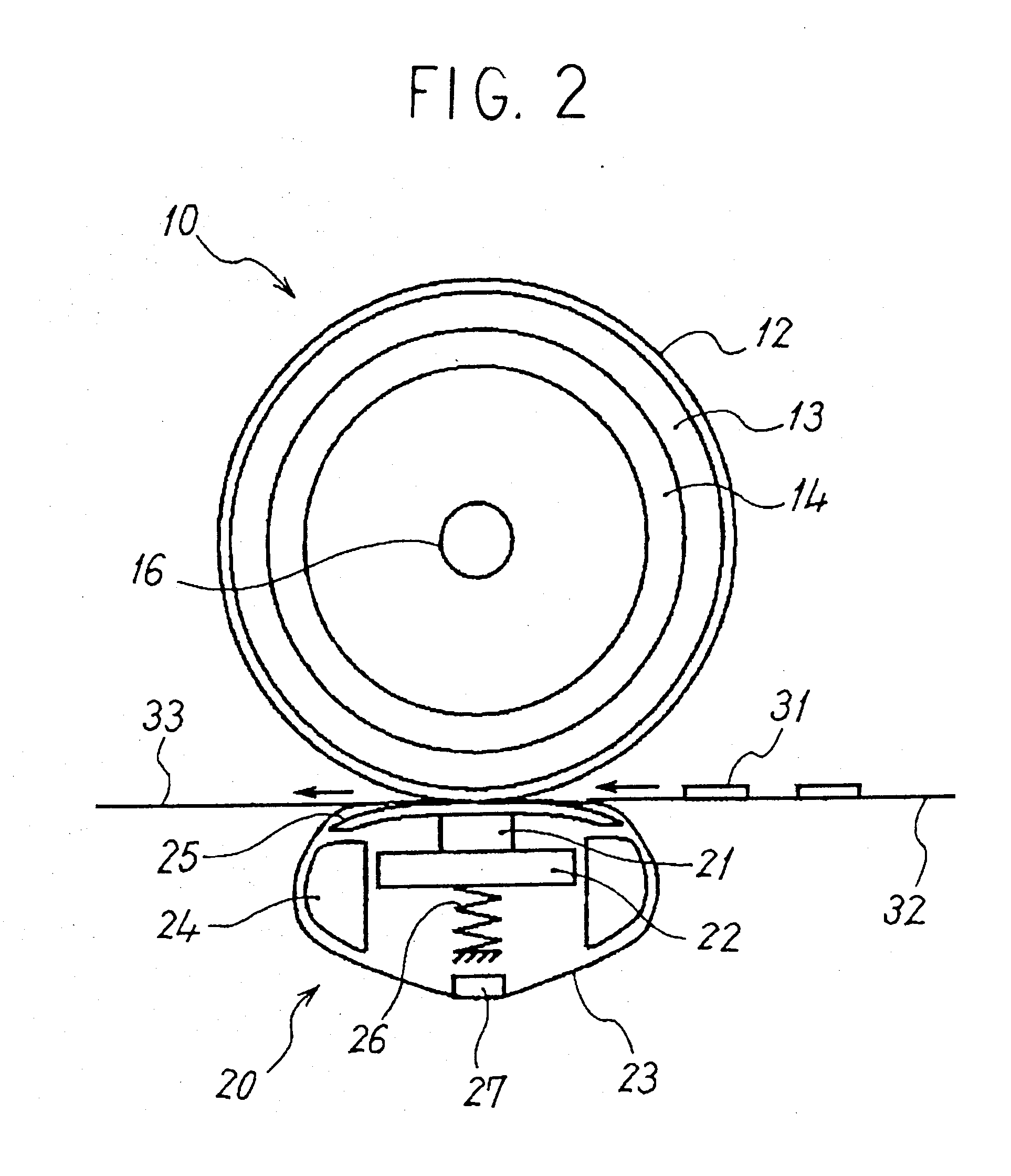
[0024] An embodiment of an image forming apparatus that uses the present invention will be explained in detail below by referring to the figures.

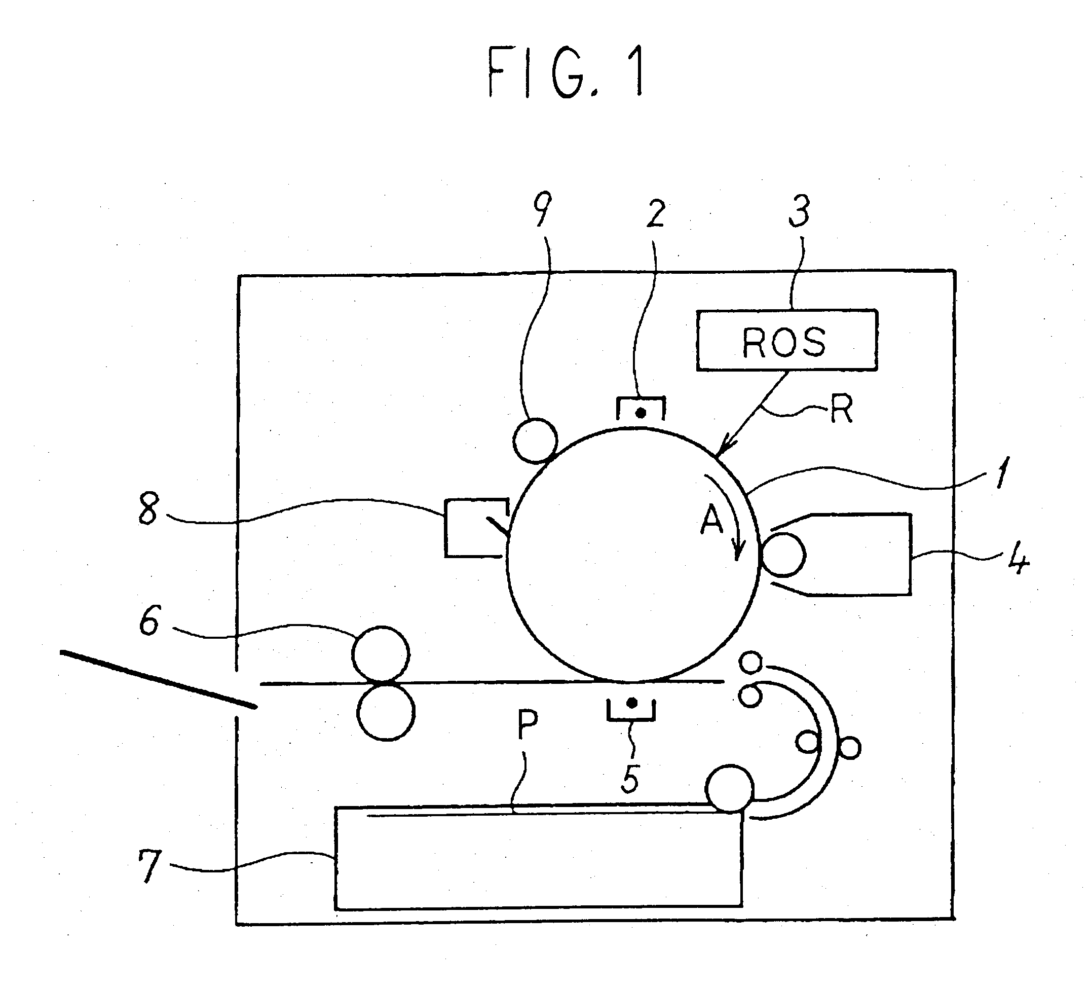
[0025]FIG. 1 shows a simplified constitution of an image forming apparatus of this embodiment. This image forming apparatus comprises a drum-shaped photoconductive member 1 as an image carrier that rotates in the direction of arrow A. Surrounding the photoconductive member 1, the image forming apparatus comprises a Scorotron charging device 2, which charges the surface of the photoconductive member 1; an ROS (laser output portion) 3, which exposes the charged surface of the photoconductive member 1 with exposure light R, which is modulated by image information, and forms an electrostatic latent image on the photoconductive member 1; a developing device 4, which develops the electrostatic latent image on the photoconductive member 1 with toner to form a toner image on the photoconductive member 1; a transfer device 5, which transfers the to...


PUM


Abstract

A low-heat loss, belt nip-type fixing device achieves good recording medium separation performance without increasing the size of the device, prevents image misalignment, and achieves a high-quality image without placing a major burden on the recording medium. This fixing device comprises a heat-fixing roller having an elastic layer and a heat source; and a pressurizing unit having an elastic member with a flat surface for pressing an endless member. The endless member conveys a recording medium, against the elastic layer. A pressurizing spring biases the elastic member toward the side of the recording medium. Biasing is carried out using the pressurizing spring such that the amount of deformation of the elastic member approaches the saturation region (maximum amount of deformation) inside a region of a nip portion, which is formed between the elastic layer of the heat-fixing roller and the endless member of pressurizing unit, and through which is passed a recording medium carrying an unfixed toner image.

Description


Claims


Application Information

Patent Timeline
Owner RICOH KK
Why Eureka
Try Eureka