Condensate pump

a condensate pump and condensate technology, applied in the direction of positive displacement liquid engines, heating types, lighting and heating apparatuses, etc., can solve the problem of reliability over many years, and achieve the effect of reducing maintenance requirements, preventing vibration transmission, and being easy to observ

Inactive Publication Date: 2007-09-27
DIVERSITECH
View PDF20 Cites 24 Cited by
  • Summary
  • Abstract
  • Description
  • Claims
  • Application Information

AI Technical Summary

Benefits of technology

[0006] With respect to installation of the condensate pump, the condensate pump of the present invention includes wall hangers attached to the reservoir so that the pump can be mounted off of the floor in an elevated position for ease of installation and subsequent access. The top assembly has four openings, one at each corner, to accommodate a discharge tube from the HVAC evaporator. In addition, the top assembly can be reversed with respect to the reservoir thus offering installation flexibility to accommodate, for example, the placement of the electric service with respect to the discharge tube from the evaporator. Further, the condensate pomp has an automatic voltage sensing circuit that automatically adapts the control circuitry and the pump motor to accommodate either 120 volts or 240 volts. Consequently, installation personnel do not have to rewire the pump to accommodate the voltage that is available at the site.
[0007] With respect to maintenance, the condensate pump of the present invention includes various features to assist both in the reduction of maintenance requirements and to assist when maintenance is required. Of particular importance, the reservoir has tube holders that extend into the reservoir from each of the four openings in the top assembly. The tube holders insure that the discharge tube from the evaporator does not bottom out in the reservoir and thus restrict the flow of condensate water from the evaporator into the reservoir of the condensate pump. The reservoir is made of a clear plastic material so that the water level in the reservoir can be readily observed without removing the top assembly. Further, the condensate pump of the present invention has a power light so that maintenance personnel can readily determine whether the condensate pump has power or not. The condensate pump also has an audible alarm that is sounded when the condensate water reaches an above normal level that indicates that the pump has stopped working. In addition, the control circuitry of the condensate pump can shut off the HVAC system when an alarm condition is detected.
[0008] With respect to quiet operation, the condensate pump has rubber feet that support the condensate pump on a support surface to inhibit the transmission of vibration to the surrounding structure. Further, the motor and impeller for the condensate pump are mounted on a rubber bushing to further isolate any noise or vibrations generated by the motor from the surrounding environment.

Problems solved by technology

Condensate pumps are often located in extreme environments and subjected to moisture, heat, and cold.
Moreover, condensate pumps are often installed in inaccessible locations where maintenance is difficult, and therefore reliability over many years is necessary.
Further, the condensate water in the reservoir of the condensate pump provides an environment for growth of algae, spores, and other contaminants that can produce an unhealthy environment in the building where the condensate pump is located.

Method used


Image

  • Condensate pump
  • Condensate pump
  • Condensate pump

Examples


Embodiment Construction

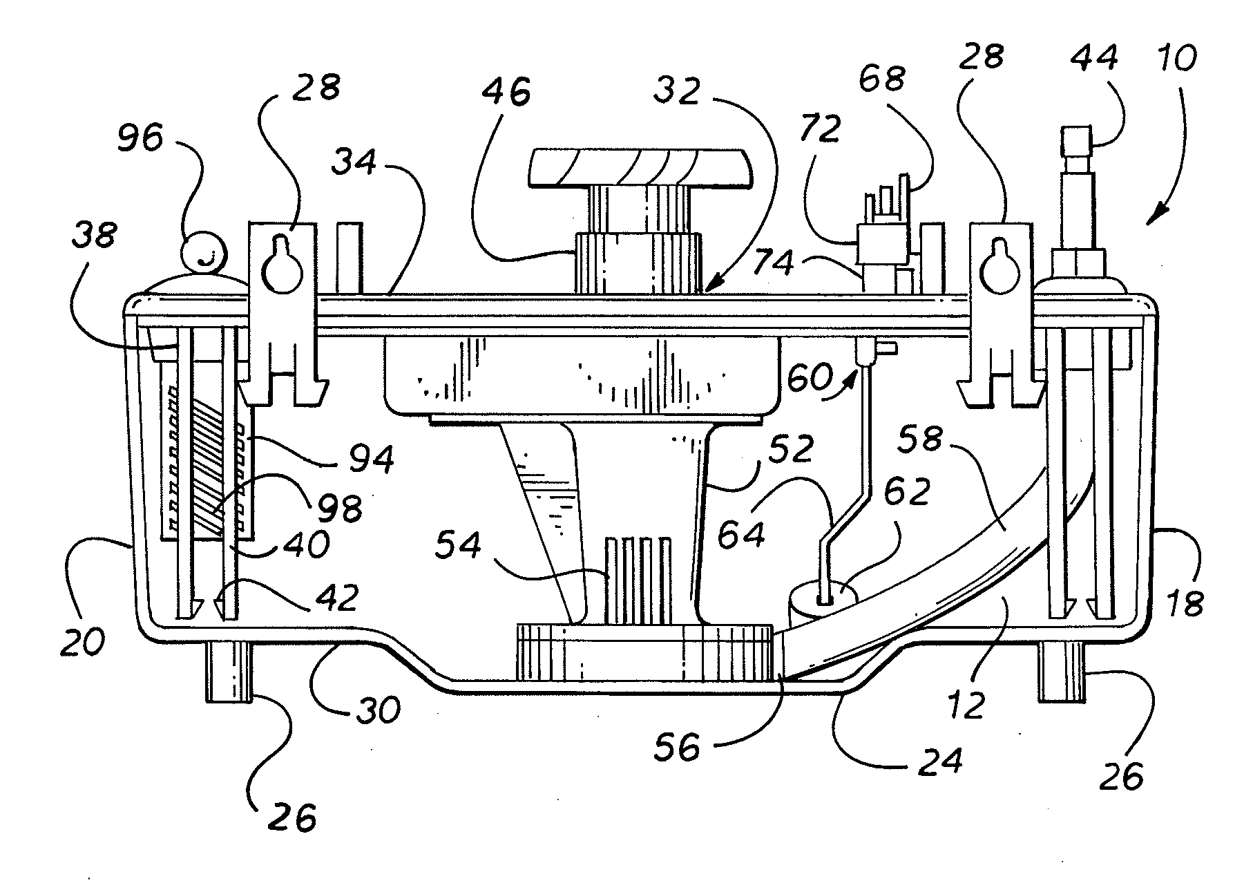
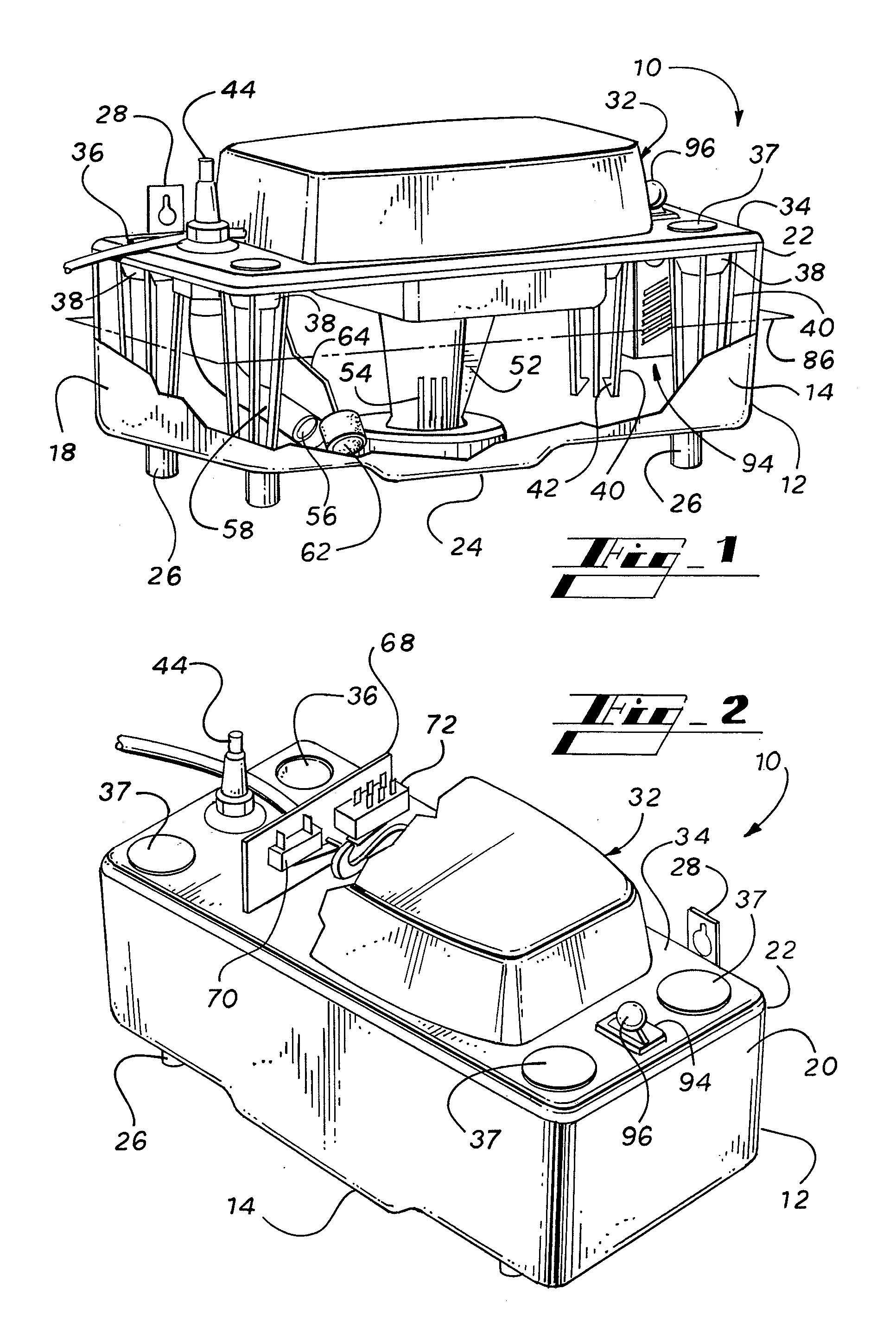
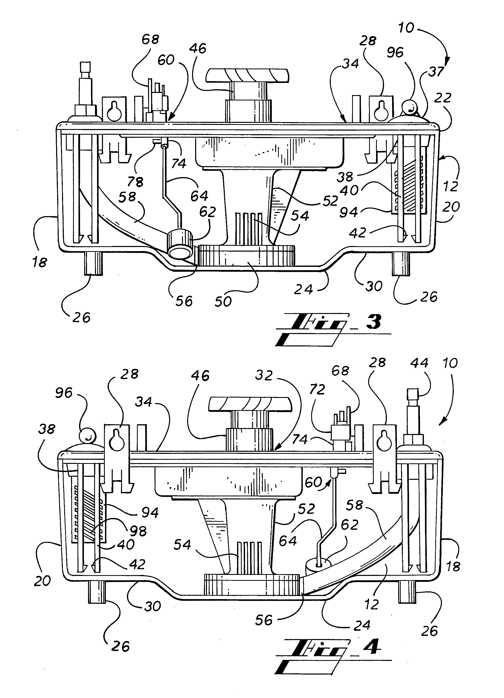
[0020] Turning to FIG. 1, a condensate pump 10 comprises a reservoir 12 and a top assembly 32. The reservoir 12 comprises a water tight container with an open top defined by a periphery. In on embodiment the reservoir comprises a front panel 14, a back panel 16, a left side panel 18, a right side panel 20, and a bottom panel 30. The reservoir may be of any geometric shape. The reservoir 12 has rubber support legs 26 located on the four corners of the bottom panel 30. The reservoir 12 further has a flange 22 around the top periphery on which the top assembly 32 rests. In addition, hanger brackets 28 are mounted to the reservoir on the back panel 16. The hanger brackets 28 are used to mount the reservoir 12, on a wall or other elevated support in order to make later access to the condensate pump 10 in some cases easier. The reservoir 12 is constructed of a clear plastic material, such as polypropylene, so that the water level in the reservoir can be observed without removing the top a...


PUM


Abstract

A condensate pump for an HVAC system includes a reservoir with a top assembly, which includes control electronics, a pump motor, and a pump impeller, mounted on top of the reservoir. The condensate pump includes wall hangers. The top assembly has a top cover with four inlet openings, and the top cover is reversible to accommodate placement of the electric service and the evaporator tube. The top cover has tube holders that extend into the reservoir so that the evaporator tube does not bottom out in the reservoir. The reservoir is made of clear plastic so that the water level can be readily observed. The condensate pump has control circuitry that can shut off the HVAC system or sound an alarm when the pump fails. The condensate pump has a drawer for biostat tablets. The drawer passes through the top assembly and extends into reservoir.

Description

FIELD OF THE INVENTION [0001] This invention relates to a condensate pump that collects condensate water from the evaporator of an HVAC system and pumps the condensate water to another location for proper disposal. BACKGROUND OF THE INVENTION [0002] A condensate pump is used in an HVAC system to collect condensate water from the evaporator of the HVAC system and to pump the condensate water to a remote location for disposal. Particularly, the condensate pump typically comprises a reservoir, a float for detecting the level of condensate water in the reservoir, and a pump controlled by the float for pumping the water out of the reservoir to the remote location. [0003] Condensate pumps are often located in extreme environments and subjected to moisture, heat, and cold. Moreover, condensate pumps are often installed in inaccessible locations where maintenance is difficult, and therefore reliability over many years is necessary. Further, the condensate water in the reservoir of the conde...

Claims


Application Information

Patent Timeline
Patent Type & Authority Applications(United States)
IPC IPC(8): F04B49/00
CPCF04D13/16F24F13/222F04D15/0218
Inventor WARD, CHARLES BARRY
Owner DIVERSITECH
Why Eureka
Try Eureka