Fuel Cell Power Generation System

Inactive Publication Date: 2007-09-27
PANASONIC CORP
View PDF11 Cites 13 Cited by
  • Summary
  • Abstract
  • Description
  • Claims
  • Application Information

AI Technical Summary

Benefits of technology

[0028] The present invention has the construction as described above, and provides a fuel cell power generation system configured to execute operation control so as to ensure economic efficiency depending on the degree of degradation or abnormality of fluid supply devices that is associated with the fuel cell power generation system, for example, cooling water of a fuel cell.

Problems solved by technology

When abnormality has occurred in, for example, a fuel cell stack, in the fuel cell power generation system, failure or the like is likely to occur in the devices if the operation is continued without any change.
If circulation of the cooling water is impeded by abnormality of the pump, etc, then the fuel cell may be in some cases severely damaged by heat.

Method used


Image

  • Fuel Cell Power Generation System
  • Fuel Cell Power Generation System
  • Fuel Cell Power Generation System

Examples


embodiment 1

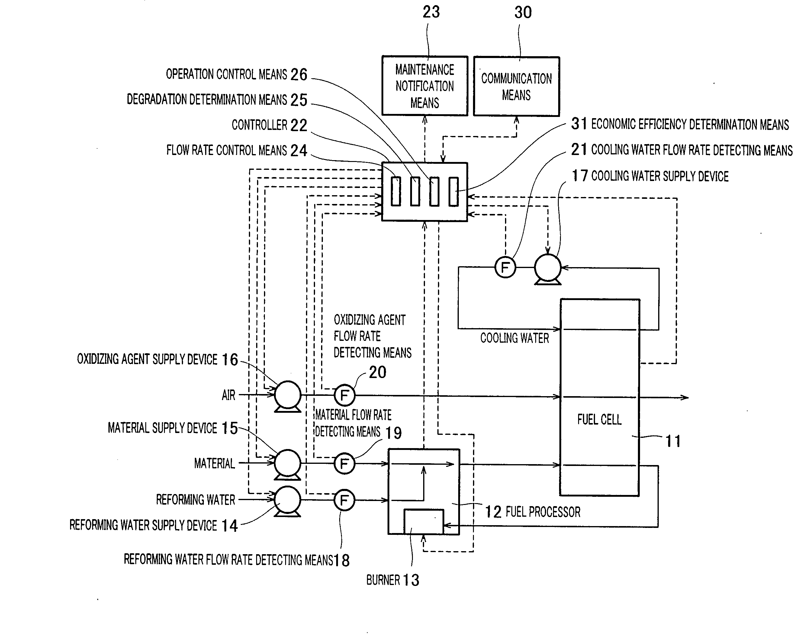
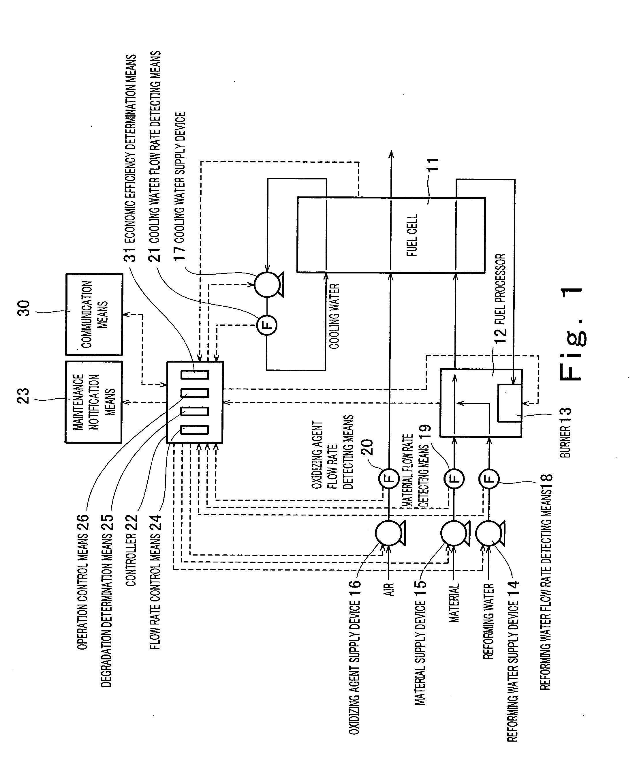
[0071]FIG. 1 is a block diagram schematically showing a construction of a fuel cell power generation system according to a first embodiment of the present invention. Hereinbelow, hardware and a control system in the fuel cell power generation system of this embodiment will be respectively described with reference to FIG. 1.

[0072] First, the hardware will be described. As shown in FIG. 1, the hardware of this embodiment includes a fuel cell 11 that generates electric power through an electrochemical reaction using a fuel and an oxidizing agent such as air which are supplied, a fuel processor 12 that generates a gas containing hydrogen through a reforming reaction occurring between a supplied material such as a natural gas and steam generated by heating supplied reforming water and to supply the gas to the fuel cell 11 as a fuel, a burner 13 that combusts the fuel (hereinafter referred to as an off gas) that is unconsumed and exhausted from the fuel cell 11 to heat the fuel processor...

embodiment 2

[0121] In the first embodiment, it is determined whether or not the first degradation and second degradation have occurred in the objects subjected to degradation determination with reference to the table without executing control for achieving a maximum flow rate as a target value. In contrast, in the second embodiment, the degradation determination means 25 determines that the first degradation and the second degradation have occurred in the objects subjected to degradation determination if a required flow rate according to a control target value of the power output is unachievable although the control is actually attempted to achieve the required flow rate.

[0122]FIG. 11 is a block diagram schematically showing a construction of a fuel cell power generation system according to this embodiment. FIG. 12 is a block diagram schematically showing a configuration of a controller in the fuel cell power generation system according to this embodiment. Below, this embodiment will be descri...

embodiment 3

[0150] In the second embodiment of the present invention, the degradation determination means 25 determines that the first degradation and the second degradation have occurred in the objects subjected to degradation determination if the required flow rate according to the control target value of the power output is unachievable in a case where the control is actually executed to achieve the required flow rate. In contrast, in a third embodiment of the present invention, the output command value and the detection value of the fluid are stored, the flow rate in the case where the output command value is set to the upper limit is predicted using the stored result, and the degradation determination means 25 determines whether or not the first degradation and the second degradation have occurred in the objects subjected to degradation determination based on the predicted result. In the third embodiment, in addition, in a case where it is determined that first degradation has occurred in ...


PUM


Abstract

A fuel cell power generation system of the present invention comprises a fuel cell (11), an object subjected to degradation determination (14, 15, 16) which is at least one of one or more fluid supply devices (14, 15, 16) that supply fluids associated with power generation in the fuel cell, a flow rate detecting means (18, 19, 20at directly or indirectly detects a flow rate of the fluid supplied from the object subjected to degradation determination, a flow rate control means (24) that controls the flow rate of the fluid supplied from the object subjected to degradation determination, a degradation determination means (25) that determines whether or not degradation has occurred in the object subjected to degradation determination (14, 15, 16) and an operation control means (26) that controls an operation of the fuel cell power generation system, and the degradation determination means (25) determines whether or not the degradation has occurred in the object subjected to degradation determination (14, 15, 16), based on the output command value given by the flow rate control means (24) to the object subjected to degradation determination (14, 15, 16) and the detection value of the flow rate that is detected by the flow rate detecting means (18, 19, 20).

Description

TECHNICAL FIELD [0001] The present invention relates to a fuel cell power generation system. More particularly, the present invention relates to a fuel cell power generation system configured to determine whether or not degradation has occurred in fluid supply devices and to continue power generation in an allowable range or to stop an operation depending on the degree of the degradation. BACKGROUND ART [0002] To operate a fuel cell power generation system, it is necessary to supply fluids such as air or water to a reformer, a fuel cell, etc, in a required amount and without excess and deficiency. In a conventional fuel cell power generation system, the fluids are supplied by fluid supply devices such as a blower or a pump, and flow rates of the fluids are measured by flow meters (see e.g., patent document 1). FIG. 20 is a block diagram schematically showing a construction of the conventional fuel cell power generation system disclosed in the patent document 1. As shown in FIG. 20, ...

Claims


Application Information

Patent Timeline
IPC IPC(8): H01M8/04H01M8/06
CPCH01M8/04082H01M8/0438H01M8/04679Y02E60/50H01M8/04955H01M8/0612H01M8/0494
Inventor TANAKA, YOSHIKAZUNAKAMURA, AKINARIOZEKI, MASATAKAOHARA, HIDEO
Owner PANASONIC CORP
Why Eureka
Try Eureka