Conductor Pin

a technology of conductor pins and pins, which is applied in the field of conductor pins, can solve the problems of difficult to provide dimensional accuracy to the hollow member with the top panel, the difficulty of producing small hollow members with a top panel, and the difficulty of conventional conductor pins such as described above in further size reduction, etc., and achieves the effect of reducing the electric resistance between the outer and inner pin portions, easy production and easy production

Inactive Publication Date: 2007-09-27
WAKO SEIKI
View PDF8 Cites 26 Cited by
  • Summary
  • Abstract
  • Description
  • Claims
  • Application Information

AI Technical Summary

Benefits of technology

[0018] As described above, since the conductor pin of the present invention uses as a contact the tubular inner pin portion, which is a hollow member unlike the conventional solid member, so that the spring is inserted in the tubular inner pin portion, the minimum length of the conductor pin that is necessary for ensuring a desired compressible length can be reduced from that in conventional conductor pins by the length of the contact (by the length of the portion of the spring inserted in the inner pin portion serving as the contact). Thus, a very small conductor pin, which is smaller than conventional conductor pins, can be obtained.
[0019] The tubular outer pin portion and the tubular inner pin portion are formed by folding the metal plate, not by drawing the metal plate. Therefore, the small tubular outer and inner pin portions can easily be produced. Particularly, using the tubular outer and inner pin portions having their inner and outer surfaces plated with a metal, a pin plated with the metal can be easily produced. This effect is particularly outstanding when a very small conductor pin is produced.
[0020] Further, when the outer pin portion includes the elastic pressure strips, and the elastic pressure strips forcedly contact and press against the inner pin portion due to their elasticity, the electric connection between the outer pin portion and the inner pin portion via the elastic pressure strips can be ensured, and electric resistance between the outer and inner pin portions can be reduced. Therefore, necessity of conduction between the pins via the inserted spring, for example, can be eliminated.

Problems solved by technology

However, conventional conductor pins as described above have difficulty in further size reduction because of their structure.
However, a very small hollow member with a top panel is difficult to be produced, particularly it is difficult to provide dimensional accuracy to the hollow member with a top panel, through a conventional drawing process of a metal plate, which is typically used for producing such hollow members.
Further, if the hollow member with a top panel forming the contact is, for example, plated with a metal, the hollow member cannot be produced using a metal plate plated with a metal in advance, since the metal plate is stretched through the drawing process (if a metal plate plated with a metal in advance is used, the metal plating on the stretched metal plate is cracked during the drawing process).
On the other hand, if the hollow member with a top panel is plated after the drawing process, it is difficult to provide satisfactory plating on the inner surface of the hollow member because of the very small inner diameter of the hollow member with a top panel.
Further, even if the plating could be carried out, the thickness of the plating on the inner surface cannot be measured.

Method used


Image

  • Conductor Pin
  • Conductor Pin
  • Conductor Pin

Examples


first embodiment

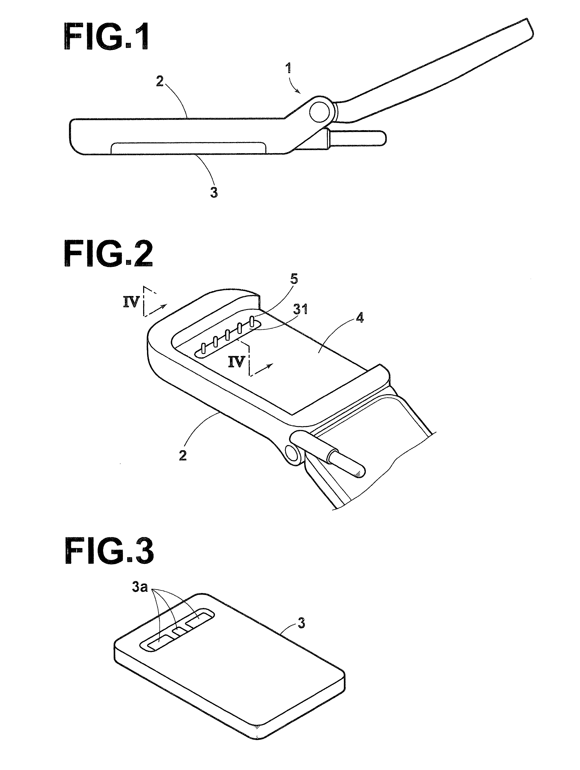
[0056]FIG. 1 is a side view illustrating a cellular phone employing a conductor pin according to the present invention, FIG. 2 is a perspective view illustrating a battery pack housing recess in the telephone body of the cellular phone from which the battery pack has been removed, and FIG. 3 is a perspective view illustrating the battery pack.

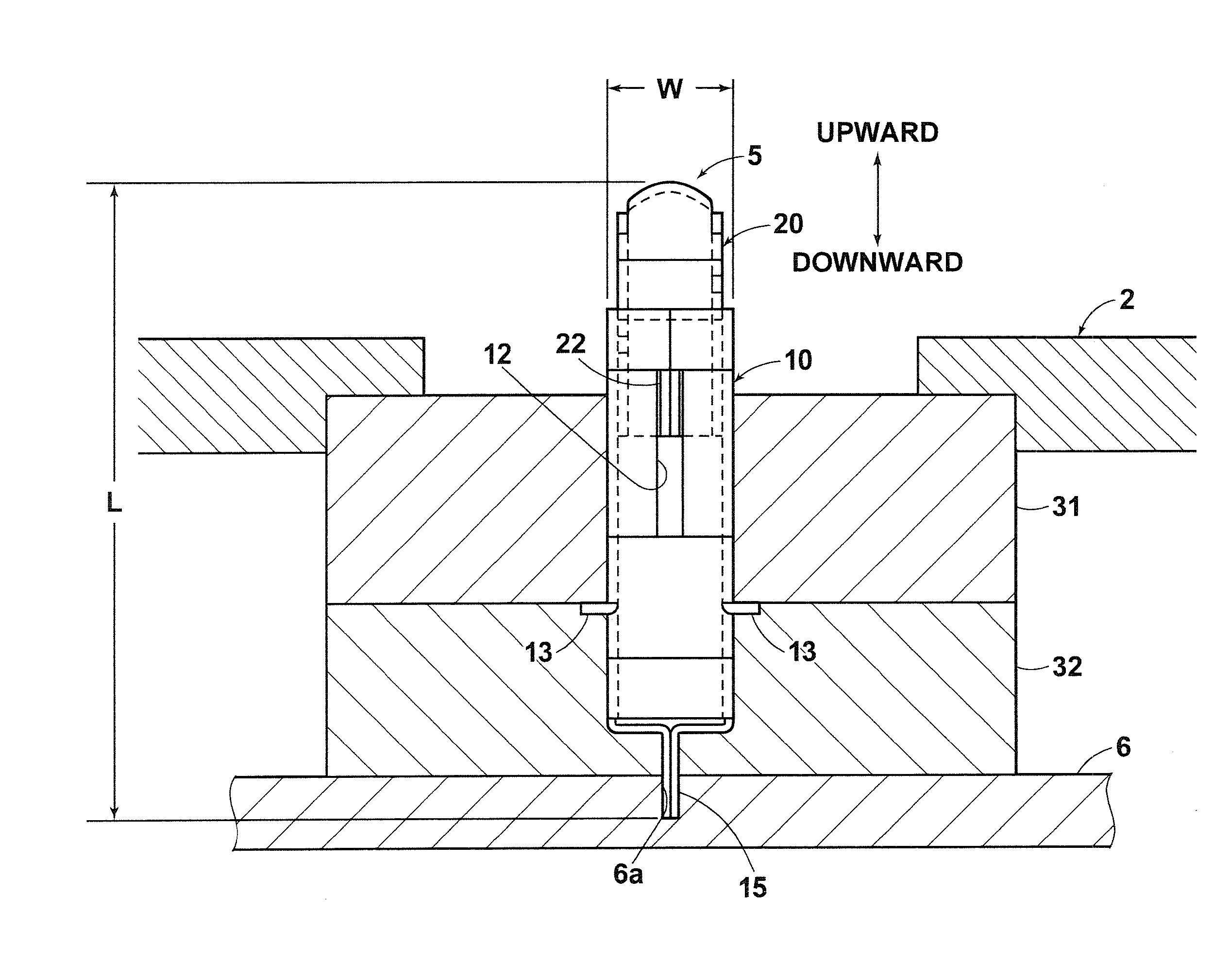
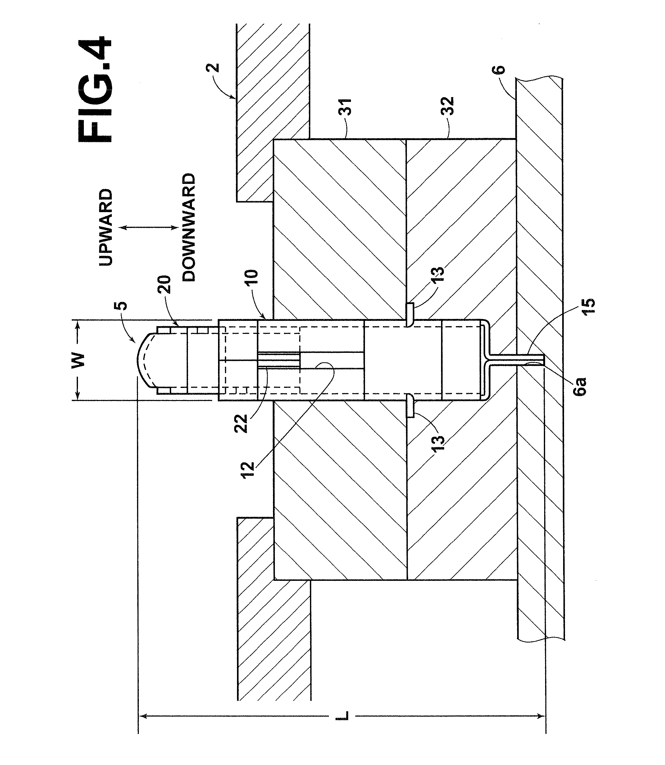
[0057] A cellular phone 1 shown in the drawing includes a telephone body 2 and a battery pack 3 removably mounted in the telephone body 2. A battery pack housing recess 4 in the telephone body 2 has five conductor pins 5 projecting therefrom. The telephone body 2 contains a print circuit board 6 (see FIG. 4 explained later) on which various electronic parts are mounted. The conductor pins 5 are fixed to the circuit board 6 and are electrically connected to the circuit board 6, i.e., conductive terminal areas of a circuit pattern on the circuit board 6. The battery pack 3 is mounted in the battery pack housing recess 4 in the telephone body 2 sh...

second embodiment

[0080] Next, a conductor pin according to the present invention will be described.

[0081]FIGS. 11A and 11B illustrate the conductor pin according to the second embodiment the present invention. FIG. 11A illustrates the uncompressed state thereof and FIG. 11B illustrates the compressed state thereof. Further, FIGS. 12A and 12B illustrate sectional views taken along line XIIA-XIIA in FIG. 11A and line XIIB-XIIB in FIG. 11B, respectively.

[0082] Similarly to the conductor pin 5 of the first embodiment, a conductor pin 7 of the present embodiment is used for allowing conduction between the battery pack 3 and the print circuit board 6 of a cellular phone. The bottom side of the conductor pin 7 is fixed to the print circuit board 6 to be electrically connected to the circuit board 6, i.e., to the conductive terminal areas of the circuit pattern on the circuit board 6, and the upper side of the conductor pin 7 contacts the conductive terminal areas of the battery pack 3 of the cellular phon...


PUM

PropertyMeasurementUnit
widthaaaaaaaaaa
lengthaaaaaaaaaa
thicknessaaaaaaaaaa

Abstract

A conductor pin placed between one member and another member and contacting the both members to electrically connect the members to each other. The conductor pin includes a tubular outer pin portion formed by folding a conductive plate material for the outer pin portion, a tubular inner pin portion formed by folding a conductive plate material for the inner pin portion and inserted in the outer pin portion slidably in the axial direction of the outer pin portion, and a conductive spring disposed in the outer pin portion and inserted in the inner pin portion to urge the inner pin portion in a direction in which the inner pin portion projects from the outer pin portion.

Description

TECHNICAL FIELD [0001] The present invention relates to a conductor pin, which is placed between two members to electrically connect the two members to allow conduction therebetween. BACKGROUND ART [0002] A conductor pin placed between two members to electrically connect the two members to allow conduction therebetween has been conventionally used in various fields or products. For example, various portable electronics devices, such as cellular phones, compact game machines, compact personal computers and PDAs, usually have a structure including a main body of the electronics device and a battery pack for supplying electric power to the main body. In this structure, electric power supply from the battery pack to the main body of the electronics device is carried out, for example, through the conductor pin placed between the battery pack and the main body. [0003] As described in Japanese Unexamined Patent Application No. 2002-56831, for example, such conventional conductor pins are f...

Claims


Application Information

Patent Timeline
Patent Type & Authority Applications(United States)
IPC IPC(8): H01R13/24H01M2/10H01M2/30H04M1/02H04M1/23
CPCH01M2/1066H01R13/2421H01R12/714H04M1/0262H04M1/0214Y02E60/10H01R13/24H04M1/23
Inventor ITO, KUNIO
Owner WAKO SEIKI
Why Eureka
Try Eureka