Cavity enlarger method and apparatus

a technology of enlarging and enlarging the body cavity, which is applied in the field of medical devices, can solve the problems of pain or injury to the patient, difficulty in enlarging or distending certain organs, vessels, and/or body cavities of a patient without causing discomfort, and difficulty for the operator to perform additional procedures

Inactive Publication Date: 2007-09-27
NOBLES ANTHONY A +1
View PDF4 Cites 78 Cited by
  • Summary
  • Abstract
  • Description
  • Claims
  • Application Information

AI Technical Summary

Benefits of technology

[0007] The present invention relates to a device for enlarging and supporting a body cavity. One embodiment of the device comprises a tubular, distending balloon having first and second distending members, spaced apart from one another, wherein the distending members are inflatable. A tubular connector interconnects the first and second distending members and forms a conduit which allows for unimpeded passage of objects and biological material through the balloon. Another embodiment of the device comprises a tubular, inflatable balloon, having a distal end, a proximal end, at least one central lumen, an outer surface and an inflation tube. The inflation tube is attached to the proximal end of the balloon and is in fluid communication with the balloon. The balloon is adapted to be inserted into a body cavity in a deflated or semi-deflated state. The balloon is further adapted to be inflated to an inflated state once inserted inside the body cavity. As the balloon is inflated, the outer surface of the balloon expands and distends the body cavity while the central lumen allows for unimpeded passage of objects, such as medical instruments, to pass through the balloon.

Problems solved by technology

Currently, it is difficult to enlarge or distend certain organs, vessels, and / or body cavities of a patient without causing discomfort, pain or injury to the patient.
For example, using a metallic speculum to enlarge a patient's vagina for a Pap smear procedure often causes discomfort to the patient because the speculum is rigid, cold, and non-conforming to anatomy.
In addition, the operator of a speculum often is required to hold the speculum in the patient, thereby making it difficult for the operator to perform additional procedures.

Method used


Image

  • Cavity enlarger method and apparatus
  • Cavity enlarger method and apparatus
  • Cavity enlarger method and apparatus

Examples


Embodiment Construction

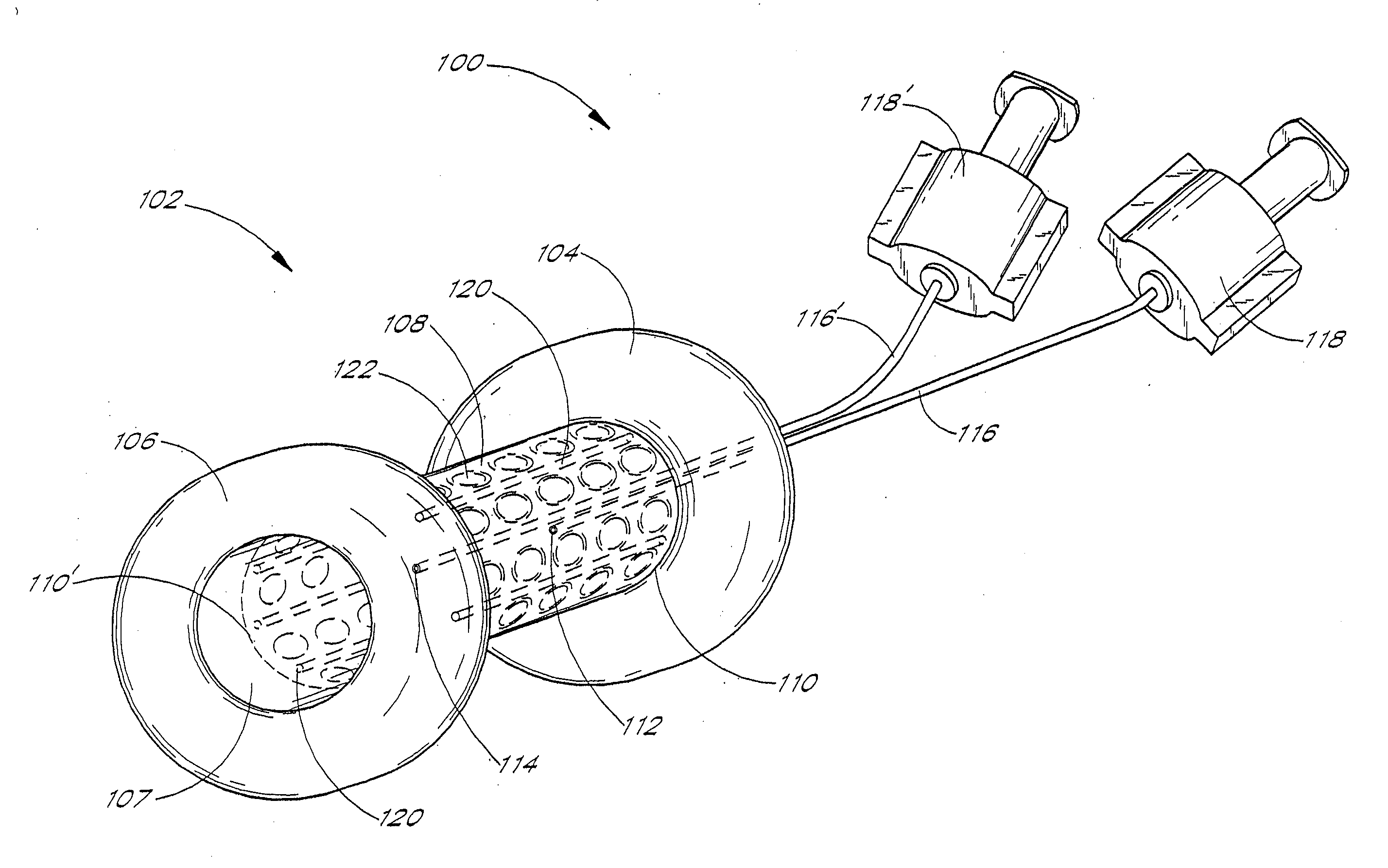
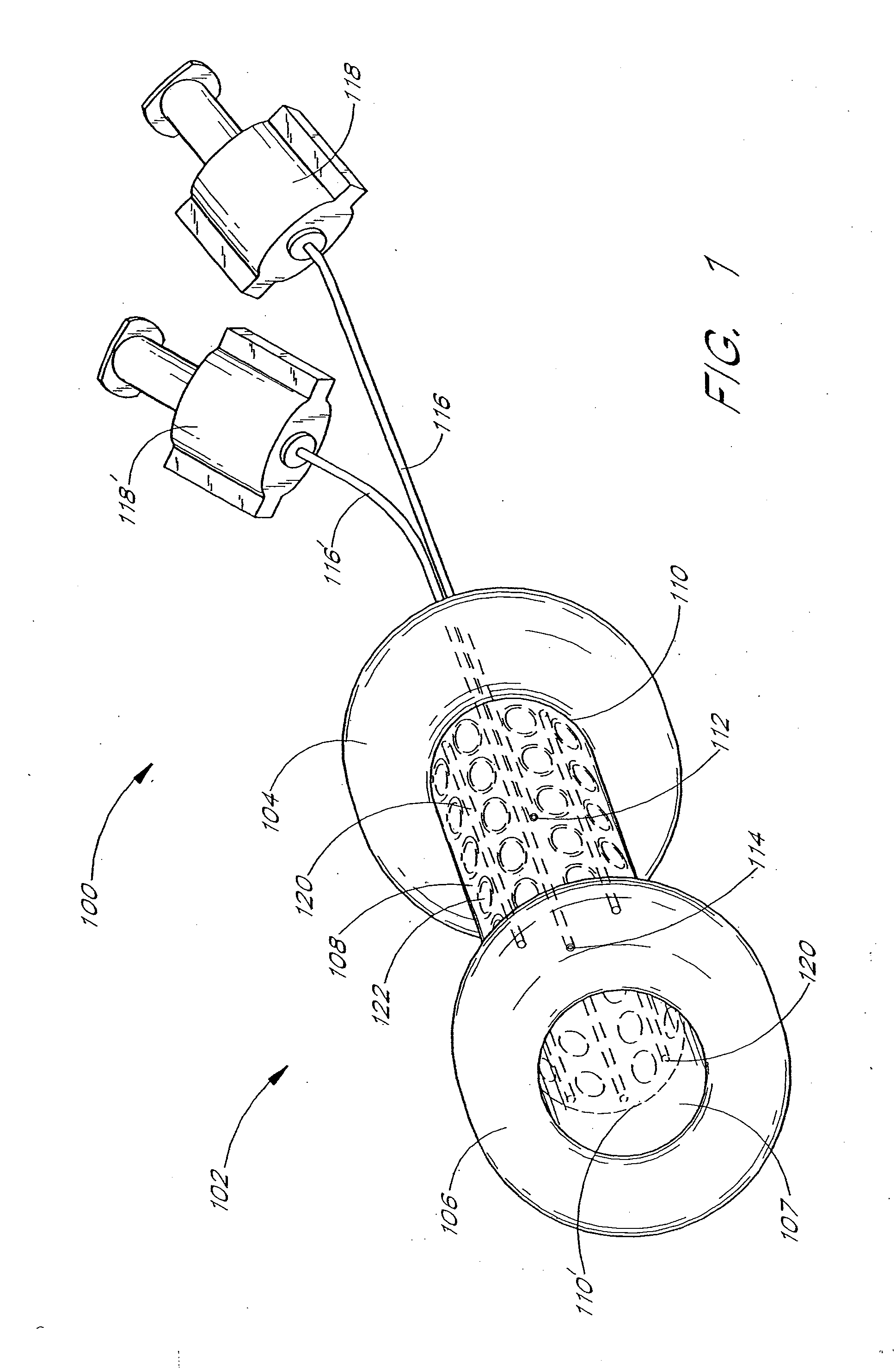
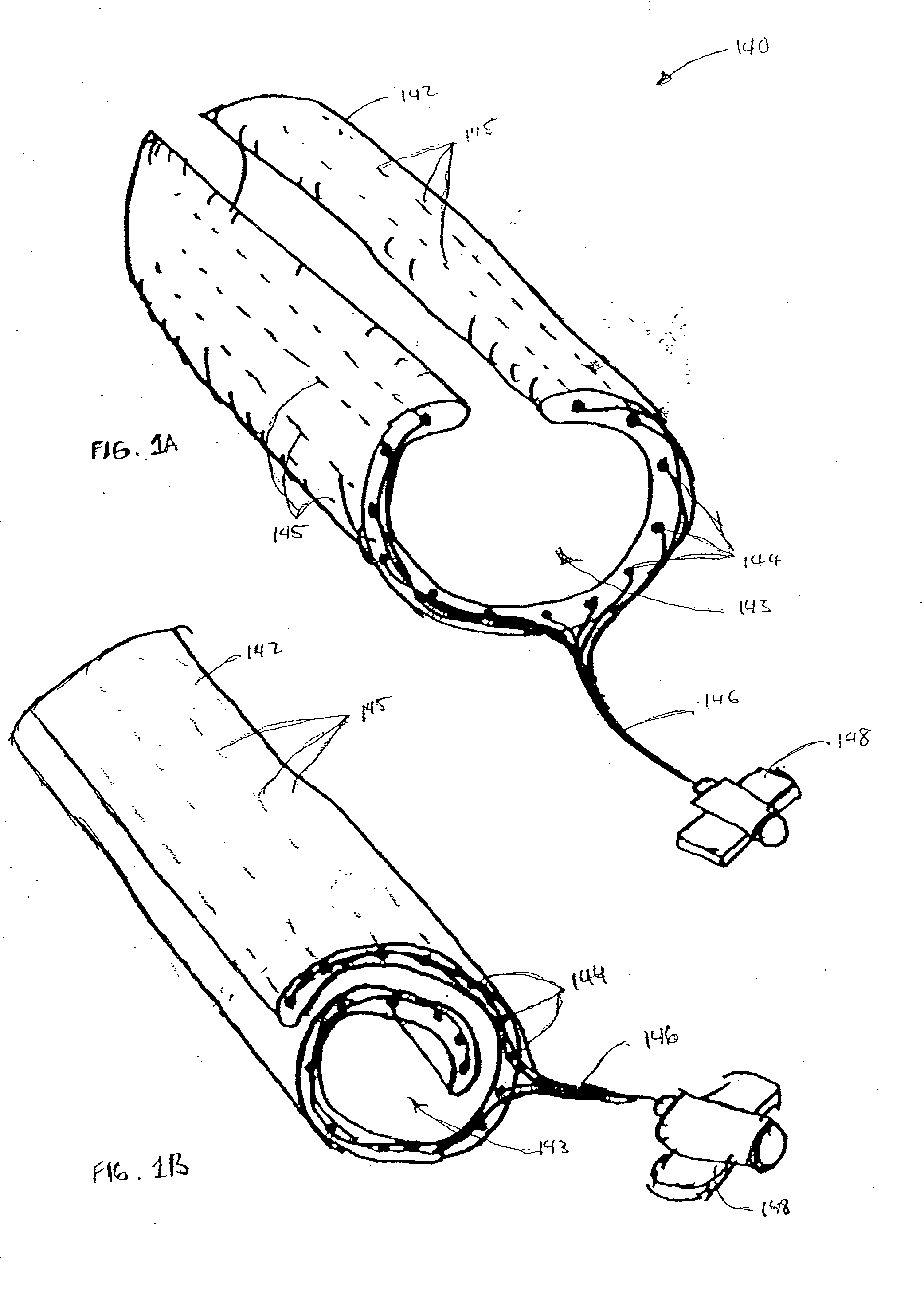
[0054] The preferred embodiments of the present invention comprise a cavity enlarger adapted to enlarge, expand or support a body cavity of a patient, such as a vagina, a rectum, a urethra, a fallopian tube, an esophagus, etc. The length, diameter, and size of the apparatus are selected to conform to the anatomy of the surrounding tissue of the particular organ, lumen or body cavity. In accordance with one embodiment of the present invention, a device for enlarging a body cavity using a distending balloon is described herein. It will be appreciated that this invention should not be limited to embodiments using balloons, and thus, other embodiments, including those which employ other types of expandable devices, are also contemplated. In order to fully specify the preferred design, various embodiment specific details are set forth. It should be understood, however, that these details are provided only to illustrate the preferred embodiments, and are not intended to limit the scope of...


PUM


Abstract

A device and method for enlarging and supporting a body cavity are disclosed. One embodiment of the device comprises a tubular, distending balloon having first and second distending members, spaced apart from one another, wherein the distending members are inflatable. A tubular connector interconnects the first and second distending members and forms a conduit which allows for unimpeded passage of objects through the balloon. The balloon is adapted to be inserted into a body cavity in a deflated or semi-deflated state. When the distending members are inflated, an outer surface of the balloon exerts pressure on an interior surface of the body cavity, thereby supporting the body cavity in a distended state while allowing for unimpeded passage of medical instrument and biological material through the balloon.

Description

CROSS-REFERENCE TO RELATED APPLICATIONS [0001] This application is a continuation of U.S. patent application Ser. No. 10 / 761,969, filed Jan. 20, 2004, which is a divisional of U.S. patent application Ser. No. 09 / 772,397, filed Jan. 29, 2001, which claims the benefit of U.S. Provisional Application No. 60 / 178,974, filed Jan. 28, 2000.BACKGROUND OF THE INVENTION [0002] 1. Field the Invention [0003] This invention relates generally to medical devices. Specifically, the invention relates to a device and method for enlarging a body cavity. The device may be used, for example, to enlarge a patient's vagina to allow for performing a Pap smear procedure. [0004] 2. Description of the Related Art [0005] Currently, it is difficult to enlarge or distend certain organs, vessels, and / or body cavities of a patient without causing discomfort, pain or injury to the patient. For example, using a metallic speculum to enlarge a patient's vagina for a Pap smear procedure often causes discomfort to the p...

Claims


Application Information

Patent Timeline
Patent Type & Authority Applications(United States)
IPC IPC(8): A61M29/02A61B1/32A61B17/02A61M29/00
CPCA61B1/32A61M29/02A61B17/0218
Inventor NOBLES, ANTHONY A.MASEDA, LUIS J.
Owner NOBLES ANTHONY A
Why Eureka
Try Eureka